


Page 30
This means that you can't simply connect the two drive wheels with a shaft and hook it up to a motor. You need something trickier, called a
differential
(not the same as differential drive).
A simple variation on the car design is the tricycle design. In this design, a single wheel, instead of a pair, is used for steering.
Exotic Drives
There are three other interesting drives that should be mentioned. The first of these is
synchro drive.
In this scheme, the robot has three or more identical wheels. Each of the wheels pivots on its
vertical center. All of the wheels point in the same direction. as shown in Figure 2-11.
Figure 2-11.
Synchro drive
To turn, the robot swivels the wheels to point in a new direction. This has the interesting side effect that the robot can change direction even though its body stays oriented the same. This property
could be useful for robots that need to communicate with the computer over the IR link. The key to building synchro drive robots is a piece called a large turntable. You can order these pieces
from Pitsco
LEGO DACTA
; see Appendix A,
Finding Parts and Programming Environments,
for details.
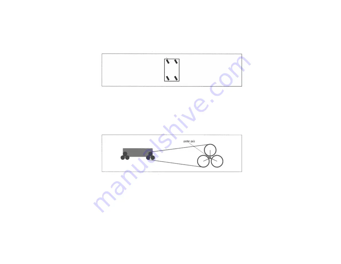
The
tri-star
wheel is another interesting idea. Figure 2-12 shows a side view of a tri-star robot and a close-up of the wheel assembly.
Figure 2-12.
Side view of the tri-star design
Page 31
Each wheel assembly is actually composed of three wheels arranged in a triangular fashion. The robot drives these wheels to move. When a large obstacle (like a step) is encountered, the entire
wheel assembly rolls on its center axis. In essence, the entire wheel assembly acts like a large triangular wheel. This large wheel size enables the tri-star design to drive over large obstacles.
Killough's platform
is an interesting variation on the wheels-within-a-wheel concept. It's really too exotic to describe here; the "Online Resources" lists two web pages that contain photographs and
diagrams of this platform.
Bumpers and Feelers
Hank uses the touch sensors to figure out when he bumps into something. But it's not really enough to put a touch sensor just on the front of your robot, because then it could be activated only in
one specific spot. Instead, Hank uses a pair of bumpers to detect touches across the entire front of the robot.
The idea of a bumper is to make a large area sensitive to touch so that the robot can detect collisions with a wide variety of objects—chair legs, walls, pets, rocks, trees, and so forth.
Содержание MINDSTORMS Robots
Страница 22: ...Page 18 The back tread wheels are anchored to the shafts with the 16t gears ...
Страница 23: ...Page 19 Page 20 Next start building support for the drive motors ...
Страница 25: ...Page 22 Attach the motor wires to output A and output C Next build the platform for the front bumpers ...
Страница 26: ...Page 23 The touch sensors are attached only by the shaft that runs through them ...
Страница 41: ...Page 41 ...
Страница 43: ...Next build the support for the light sensor ...
Страница 80: ...Page 85 Make sure the bump on the long pin is up against the 4u beam ...
Страница 82: ......
Страница 84: ...Page 89 ...
Страница 85: ...Step 14 is similar to Step 11 take a deep breath and go slowly ...
Страница 86: ...Page 90 Grabber Arm In Step 17 the half bushings go between the center block and the cams pear shaped pieces ...
Страница 87: ...Page 91 ...
Страница 88: ...Page 92 Make sure that the two sides are at the same angle They should mirror each other ...
Страница 89: ...Page 93 Page 94 ...
Страница 90: ...Structural Support Page 95 ...
Страница 91: ...Idler Wheel Page 96 ...
Страница 92: ...Page 97 Drive Motor ...
Страница 93: ...While you re putting the motor in hold on to the worm gear so it doesn t slip off Page 98 ...
Страница 94: ...Grabber Arm Motor ...
Страница 95: ...Page 99 ...
Страница 96: ...Page 100 RCX Attach the RCX on both sides as shown Page 101 ...
Страница 158: ......
Страница 159: ...Page 175 The 16t gears are nestled inside the tread wheels ...
Страница 160: ...Page 176 ...
Страница 161: ...Page 177 Attach the motors to output A and output C as shown Page 178 ...
Страница 162: ...The light sensor which is mounted on the bumper is attached to input 2 The touch sensor goes on input 1 Page 179 ...