


Page 220
Figure 11-2.
A mercury switch
The mercury switch works just like a contact switch. When the switch is correctly oriented, the two leads are shorted together. It's basically a primitive angle sensor. In a thermostat, for example,
the mercury switch is used to indicate two states: either it's less than the desired angle or greater than the desired angle. The desired angle in a thermostat corresponds to the temperature setting
you've chosen.
Light Sensors
The light sensor that comes with RIS is a powered device; it emits light using an LED, and senses light with a
phototransistor.
The phototransistor responds to changes in light, but it must be
powered. A slightly simpler device, a
photoresistor,
can be used to build a passive light sensor. The photoresistor responds to changes in light by changing its resistance. This is a perfect candidate
for an RCX sensor. Basically all you have to do is hook up the leads of the photoresistor to one of the RCX inputs.
Radio Shack sells Cadmium Sulfide (CdS) photoresistors that work well as robot sensors. Figure 11-3 shows a photograph of one such photoresistor mounted in a brick using the machine screw
mounting method.
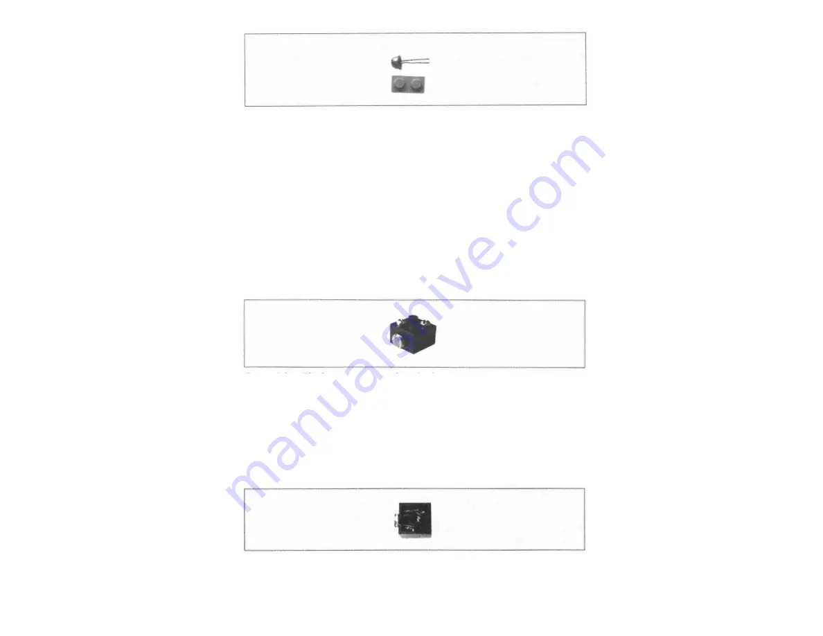
Figure 11-3.
A CdS photoresistor mounted in a brick
The machine screws were mounted on the brick as described previously. All that remained was to mount the photoresistor itself in the brick. To do this, two holes were made for the leads of the
photoresistor. Then the leads were threaded through to the inside of the brick and soldered to the wires that were already there. These wires were previously attached to the screws. The extra wire
can be pushed up inside the brick. Figure 11-4 shows a photograph of the bottom of the same photoresistor sensor.
Page 221
Figure 11-4.
A bottom view of the CdS photoresistor sensor
You can make holes for the sensor leads using a small drill. If you don't have one of these, you can heat a wire with a soldering iron and push it through the side of the brick, creating a small hole.
Содержание MINDSTORMS Robots
Страница 22: ...Page 18 The back tread wheels are anchored to the shafts with the 16t gears ...
Страница 23: ...Page 19 Page 20 Next start building support for the drive motors ...
Страница 25: ...Page 22 Attach the motor wires to output A and output C Next build the platform for the front bumpers ...
Страница 26: ...Page 23 The touch sensors are attached only by the shaft that runs through them ...
Страница 41: ...Page 41 ...
Страница 43: ...Next build the support for the light sensor ...
Страница 80: ...Page 85 Make sure the bump on the long pin is up against the 4u beam ...
Страница 82: ......
Страница 84: ...Page 89 ...
Страница 85: ...Step 14 is similar to Step 11 take a deep breath and go slowly ...
Страница 86: ...Page 90 Grabber Arm In Step 17 the half bushings go between the center block and the cams pear shaped pieces ...
Страница 87: ...Page 91 ...
Страница 88: ...Page 92 Make sure that the two sides are at the same angle They should mirror each other ...
Страница 89: ...Page 93 Page 94 ...
Страница 90: ...Structural Support Page 95 ...
Страница 91: ...Idler Wheel Page 96 ...
Страница 92: ...Page 97 Drive Motor ...
Страница 93: ...While you re putting the motor in hold on to the worm gear so it doesn t slip off Page 98 ...
Страница 94: ...Grabber Arm Motor ...
Страница 95: ...Page 99 ...
Страница 96: ...Page 100 RCX Attach the RCX on both sides as shown Page 101 ...
Страница 158: ......
Страница 159: ...Page 175 The 16t gears are nestled inside the tread wheels ...
Страница 160: ...Page 176 ...
Страница 161: ...Page 177 Attach the motors to output A and output C as shown Page 178 ...
Страница 162: ...The light sensor which is mounted on the bumper is attached to input 2 The touch sensor goes on input 1 Page 179 ...