58
Commissioning
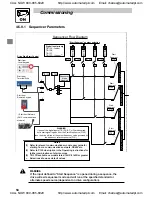
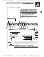
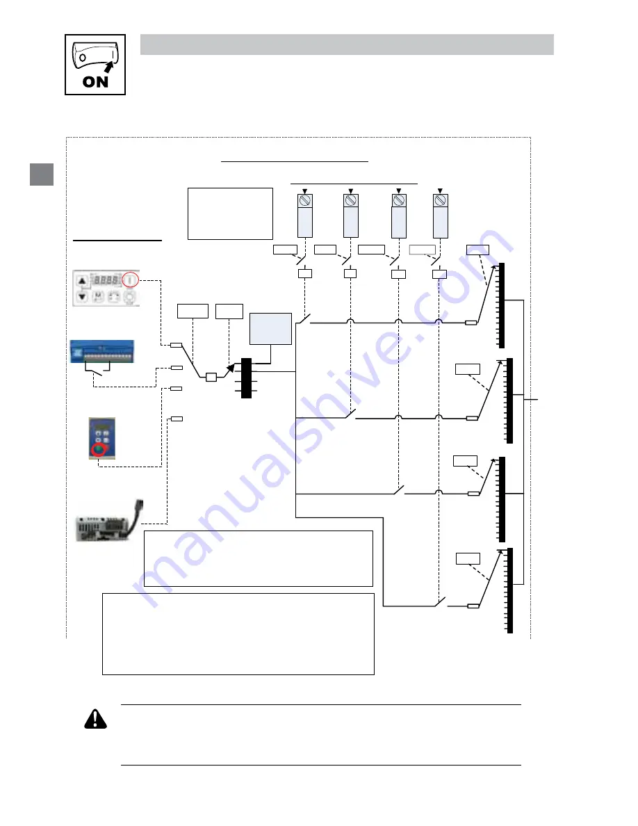
4.5.9.1 Sequencer Parameters
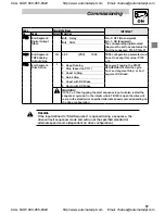
WARNING
If the input defined to “Start Sequence” is opened during a sequence, the
drive will exit sequencer mode and will run at the specified standard or
alternate speed source (dependent on drive configuration).
Drive Stop/Start Control
TB-13
C
TB-13
B
TB-13
A
1
2
3
4
5
6
7
8
9
10
11
12
13
14
15
16
P701
P702
1
2
3
4
5
6
7
8
9
10
11
12
13
14
15
16
1
2
3
4
5
6
7
8
9
10
11
12
13
14
15
16
P703
P
121
24
P
122
24
P
123
24
3
2
3
P
700
0
2
Sequencer
mode
disabled
1
Start
Segment
Start
Segment
Start
Segment
“Start Segment” number selection
WARNING
If none of the digital inputs (TB-13A,B,C or D) are asserted
but a start signal is given from the Start/Stop source (P100)
then the drive will run at the output frequency value governed by
the frequency reference source (P101).
Start from
Local Keypad
Start from
Terminal Strip
0
1
2
(2)
P
100
Start from
Remote Keypad
3
(1)
Start from Network
(SMV communications
module)
Notes
(1)
Refer to relevant communications module user guide for starting from a
communications network, RS485 etc..
(2)
Refer to P100 description in the SMV Operating instructions for further
combinations of start sources.
> Selections shown as default values
Digital Input priority:
TB-13A - Lowest
TB-13B
TB-13C
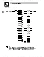
Sequencer Flow Diagram
TB-13
D
24
P
124
P704
1
2
3
4
5
6
7
8
9
10
11
12
13
14
15
16
Segment
Start
TB-13D - Highest
(3)
TB-13D available on SMV models rated 15HP (11kW) or greater.
(3)
Notes
(1) Refer to relevant communications module user guide for
starting from a communications network, RS485 etc.
(2) Refer to P100 description in the Operating instructions for
further combinations of start sources.
(3) TB-13D available on models rated 15HP (11kW) or greater.
> Selections shown as default values
CALL NOW 800-985-6929
http://www.automatedpt.com
Email: [email protected]
CALL NOW 800-985-6929
http://www.automatedpt.com
Email: [email protected]

