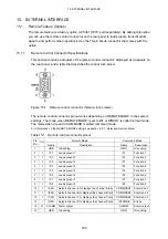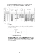
14. STATUS DISPLAY
171
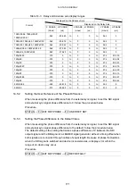
Table 14-3 Delay and Advance axis display ranges
Displayed on the Advance Axis
Displayed on the Delay Axis
Format
V PHASE
(Lines)
H PHASE
(us)
V PHASE
(Lines)
H PHASE
(us)
V PHASE
(Lines)
H PHASE
(us)
1080i/59.94, 1080p/29.97,
1080PsF/29.97
-562 -29.645
to
0
0 to 562
0
1080i/60, 1080p/30, 1080PsF/30 -562 -29.616
to
0
0 to 562
0
1080i/50, 1080p/25, 1080PsF/25 -562 -35.542
to
0
0 to 562
0
1080p/23.98, 1080PsF/23.98
-562 -37.060
to
0
0 to 562
0
1080p/24, 1080PsF/24
-562
-37.023
to
0
0
to
562
0
720p/59.94 -375
0
to
0
0
to
374
22.230
720p/60 -375
0
to
0
0
to
374
22.208
720p/50 -375
0
to
0
0
to
374
26.653
720p/29.97 -375
0
to
0
0
to
374
44.475
720p/30 -375
0
to
0
0
to
374
44.430
720p/25 -375
0
to
0
0
to
374
53.319
720p/23.98 -375
0
to
0
0
to
374
55.597
720p/24 -375
0
to
0
0
to
374
55.542
525i/59.94 -262
-63.518
to
0
0
to
262
0
625i/50 -312
-63.962
to
0
0
to
312
0
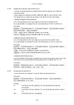
14.5.2
Setting the User Reference of the Phase Difference
When measuring the phase difference from the external sync signal, to set the SDI signal
and external sync signal phase difference to 0, follow the procedure below.
Procedure
STATUS
→
F•3 EXT REF PHASE
→
F•1 USER REF SET
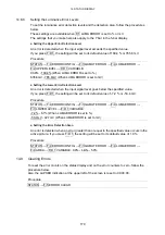
14.5.3
Setting the Phase Difference to the Default Value
When measuring the phase difference from the external sync signal, to set the SDI signal
and external sync signal phase difference to the default, follow the procedure below.
The default setting is the setting that makes a phase difference of 0 between the SDI
output signal and the BB signal of a LEADER signal generator without a timing offset when
both signals are connected through cables of equal length. Because of phase fluctuations
when the SDI signal is switched and device inconsistencies, a display error within the
range of ±3 clocks may occur.
Procedure
STATUS
→
F•3 EXT REF PHASE
→
F•2 REF DEFAULT


