9. PICTURE DISPLAY
88
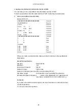
Keywords
Be sure to put the keyword lines before the data lines and to enter a keyword without
anything preceding it at the beginning of each keyword line.
NAME
The LV 5381 displays the eight characters that follow
the separator (colon) as the name of the correction
table. After the separator, enter the correction table
name using letters of the alphabet (A to Z; uppercase
and lowercase), numbers (0 to 9), and underscores (_).
You can enter up to 10 characters.
TYPE
This is a code for identifying the file type. Enter a zero
after the separator (colon).
Data
From the start of a line, enter the input value, a separator, and then the output value, in
that order.
Input Value
Enter values from 0 to 4095 (12 bits), increasing the
value by one for each line.
A luminance level of 100 % is defined as 940 (10 bits)
× 4 = 3760 (12 bits).
A luminance level of 0 % is defined as 64 (10 bits) × 4
= 256 (12 bits).
Separator
Enter a single tab code.
Output Value
Enter a value from 0 to 65535 (16 bits).
2. Save the user-defined correction table to USB memory, and connect the USB memory to
the LV 5381.
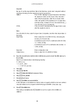
Save the correction table in the following directory.
USB memory
└
LV5381_USER
└
TEST.CLT (example)
3. Press
PIC.
4. Press
F•5
CINELITE.
5. Press F•1 CINELITE DISPLAY, and select f Stop.
6. Press F•2 f Stop SETUP.
7. Press F•4 next menu.
8. Press F•1 GAMMA, and select USER-A.
In this example, a user-defined correction table is copied to USER-A, but user-defined
correction tables can be copied to USER-B through USER-E in the same way.
9. Press F•2 GAMMA FILE.
This setting is available when F•1 GAMMA is set to an option from USER-A to
USER-E.

