
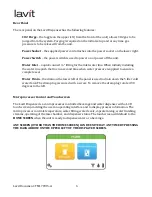

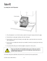


Lavit Document: TM170915-‐A
8
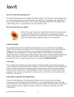
Disinfection
The cold tank water system is disinfected every 24 hours at 3 am (factory setting). The Ozone
Generator will turn on for 1 hour and as the generator runs, ozone is injected into the cold tank by
means of the cold tank circulation pump. This ensures that the entire content of the cold tank is
exposed to ozone every 24 hours. The ozone start time can be changed as required through the
service screen.
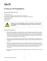
Filtration for POU installation
Lavit recommends using the Lavit ECO3 Filter for dispenser installations to a building’s main
water supply (POU). The filter is a 0.5 micron carbon block rated at 1500 gallons, and is NSF
certified to standard 42 Classes 1, chlorine taste and odor, and standard 53 cysts, lead and
asbestos. The Lavit ECO3 also has a NSF certified multi layer sediment particulate membrane to
protect the carbon block. In any known high sediment water areas please use a pre-‐sediment filter
before the machine and filter.
Antimicrobial Protection
The contact parts of the Lavit Dispenser are protected by Lavit through silver ion technology. A
silver ion additive is added to the raw plastic parts as they are manufactured. This inhibits the
growth of bacteria on contact surfaces. The additive will not leach out and will be effective for the
life of the machine.
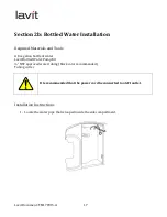
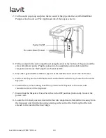
Bottled Water Installation
In addition to a POU installation, the Lavit Dispenser is designed to also work with a 5-‐gallon
bottle water supply. A bottled water installation will require the fitting of a Lavit bottle water
pump kit, which is supplied separately.
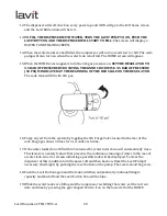
Transporting the Lavit Dispenser
The Lavit Unit should not be transported with water in either tank or with a CO
2
cylinder attached.
Please drain the unit of all water per the instructions provided in this manual before moving the
unit. The CO
2
cylinder should also be removed and the CO
2
regulator secured in place with tape.
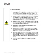
CO
2
Cylinders
CO
2
cylinders are provided to distributors and dealers by authorized Lavit distributors. Each filled
cylinder contains 1.5 pounds of liquid CO
2
which when released to atmosphere converts to a gas.
Sparkling water is created by mixing CO
2
gas in cold chilled water. Each cylinder is filled with food
grade or beverage grade CO
2
. It is imperative that a minimum of food grade gas is provided. It is
critical that distributors and dealers and their service personnel properly handle, store, and
transport filled cylinders.
Содержание LCB 100
Страница 1: ...Lavit Document TM170915 A September 20 2015 Technical Manual Lavit LCB 100 Dispenser...
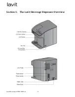
Страница 4: ...Lavit Document TM170915 A 4 Section 1 The Lavit Beverage Dispenser Overview...
Страница 52: ...Lavit Document TM170915 A 52 Appendix A Flow Diagram...
Страница 53: ...Lavit Document TM170915 A 53 Appendix B Electrical Schematic 1...
Страница 54: ...Lavit Document TM170915 A 54 Appendix C Electrical Schematic 2...
Страница 55: ...Lavit Document TM170915 A 55 Appendix D Exploded Parts Detail...
Страница 56: ...Lavit Document TM170915 A 56...
Страница 57: ...Lavit Document TM170915 A 57 Appendix D Exploded Wetted Parts Detail...
Страница 58: ...Lavit Document TM170915 A 58...