background image


USER MANUAL

 Manure spreader MKL 


 11 


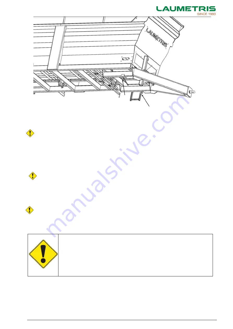
Fig. 1.4. Manure spreader fastening loops at the front and rear. 

When  the  manure  spreader  is  loaded  onto  the  transportation  platform,  the  parking  brake  must  be 

turned on. Lashing straps or chains must be connected to the transport platform through specified loops 
and tensioned. Uncouple the tractor after attaching the manure spreader. 

Attention!  When  the  manure  spreader  is  transported  on  a  platform,  it  must  be  secured  in 

accordance with safety requirements and directives. 

The  driver  of  the  vehicle  must  be  particularly  careful  during  transport,  as  the  center  of  gravity  of  the 
vehicle has risen after the manure spreader has been loaded. 
Use  only  certified  and  technically  reliable  fasteners.  Carefully  read  user's  instructions  for  proper 
mounting. 

During mounting care must be taken not to damage transportation loops or paint. The weight of the 

manure spreader is given in tables 3.1, 3.2. 

Attention! Improper securing of the fasteners can cause an accident 

1.4.2 Requirements prior to use 

Before  using  the  manure  spreader,  the  user  must  read  the  operating  instructions  and  follow  the 

instructions  provided.  During  transportation  adjust  the  driving  speed  to  the  road  conditions,  but  do  not 
exceed the maximum permitted speed. 

Attention! The user must read the operating instructions before transporting the manure spreader 

on his own.


2. GENERAL REQUIREMENTS FOR WORK SAFETY 

2.1 Symbols and definitions 


ATTENTION! 
IMPORTANT! 

This  symbol  in  the  instruction  means  to  pay  attention  to  the  safety  of  use,  i.e. 

possible breakdown or danger of injury. 

The  warning  signs  must  be  well  readable.  If  damaged,  they  must  be  replaced 

immediately. Original stickers can be purchased from UAB LAUMETRIS. 

Failure to execute this instruction may result in the breakdown of the machine or its 

separate parts. 

'Qualified' - person, is someone who has a good knowledge of work safety requirements when working 

with machinery, is able to identify potential hazards and knows how to avoid them, and has knowledge of 
providing first aid to injured people. 

The  term  “use”  shall  cover  installation,  commissioning  (preparation  for  use),  and  servicing 

(commissioning, start-up, shut-down, etc.). 

Содержание MKL

Страница 1: ...LAUMETRIS UAB TECHNIKOS STREET 4 KELERISKIAI VILLAGE KEDAINIAI DISTRICT 57343 LITHUANIA Tel 37034742390 info laumetris lt USER MANUAL FOR MANURE SPREADER MKL...

Страница 2: ...SER MANUAL Manure spreader MKL 2 Happy to become an agricultural machinery supplier of Yours Willingly efficiency of Laumetris machinery will vastly increase Your overall results Kind regards Laumetri...

Страница 3: ...____________________ _______________________________ _______________________________ Laumetris UAB Technikos street 4 Keleriskiai village Kedainiai district 57343 Lithuania Tel 37034742390 info laumet...

Страница 4: ...periods in such cases the seller must be addressed regarding the warranty claim Only claims which had been correctly completed and submitted no later than two weeks after the defect occurred can be p...

Страница 5: ...heels 13 2 3 3 Hydraulic and pneumatic systems 13 2 3 4 Periodical servicing 13 2 3 5 Driving on public roads 14 2 4 Signs and notices 14 3 TECHNICAL SPECIFICATIONS 18 4 DESIGN AND OPERATING PRINCIPLE...

Страница 6: ...rakes 48 7 2 1 Servicing of the pneumatic brake system 48 7 2 2 Adjustment of the elements of the pneumatic brake system 49 7 2 3 Servicing and adjustment of the hydraulic brake system 50 7 3 Hydrauli...

Страница 7: ...e Transporting machinery named below are manufactured in compliance with Council Directive 2006 42 EC The above declaration covers the following manure spreaders MKL XX Serijos Nr MKLXXXXXXXXXXX000 MK...

Страница 8: ...e provided that the user manual is followed Therefore this manual must be read before beginning to use the product Read the manual before using the product The user manual is the main guidance for the...

Страница 9: ...tory plate placed on the right frontal side of the frame The number is written and embossed on the frame above the statutory plate Axis statutory plate Wheel axis brand and type are marked on the axis...

Страница 10: ...spreader attended a work safety and first medical aid course and hold a tractor driver s license During work effective work safety requirements and occupational medicine safe driving and road traffic...

Страница 11: ...dent 1 4 2 Requirements prior to use Before using the manure spreader the user must read the operating instructions and follow the instructions provided During transportation adjust the driving speed...

Страница 12: ...is not turned on it is prohibited to stay between the tractor and the manure spreader or behind the manure spreader 3 When connecting the hydraulic pneumatic and electricity systems of the manure spr...

Страница 13: ...eels and adjust hub bearings and brakes only after installing protective supports under the sway beam and the axle and inserting protective wedges under the wheels of the opposite side 6 Install jacks...

Страница 14: ...cal loading capacity Usually technical loading capacity is higher than according to road regulations 7 Do not work with the manure spreader when there is more than 8 surface inclination 8 Pay attentio...

Страница 15: ...lements Information sign Marking of the place of installing jacks Warning sign Indication of slow moving vehicle Place at the rear of the body Information sign Greasing points marking Place on the cha...

Страница 16: ...anging manure transporter direction to spreading into the body controlled from the tractor Place front of the body YELLOW SUPPORT FOOT GREEN TAILGATE RED MANURE TRANSPORTER BLUE HITCH CYLINDERS Inform...

Страница 17: ...USER MANUAL Manure spreader MKL 17 Fig 2 1 Sticker position schematic...

Страница 18: ...200 Table 3 2 Technical specifications of MKL 16 18 20 Specifications may differ according different options of a product The maximum weight of the load reflects the technical load of the product it d...

Страница 19: ...L Manure spreader MKL 19 Fig 4 1 Chain transporter diagram 1 chain transporter 2 chain transporter tensioning bolts 3 chain transporter tensioning axis 4 chain transporter driving axis 5 reductor 6 hy...

Страница 20: ...hubs reduces tire wear and improves the manoeuvrability of the manure spreader The vibration of the axle trapezoidal steering rods is reduced by shock absorbers Using a manure spreader with a two axle...

Страница 21: ...he hydraulic system of the tractor Fig 4 3 Fig 4 3 The general hydraulic diagram of the manure spreader 1 chain transporter hydro motor 2 tailgate hydraulic cylinders 3 support foot hydraulic cylinder...

Страница 22: ...e customer s request hydraulic Hydraulic single line circuit braking system Fig 4 6 Hydraulic single circuit braking system schematic 1 Main valve 2 brake force control valve 3 brake hydraulic cylinde...

Страница 23: ...place or repair any worn out parts or assemblies replace any obsolete hose of the hydraulic system with new ones This shall be done every 5 years paint any scratched or damaged rusted places apply gre...

Страница 24: ...being transported project beyond the dimensions of the manure spreader follow the requirements of the traffic rules while marking of the load and ensuring safety on the road ATTENTION It is prohibite...

Страница 25: ...conveyor tension 6 4 Detaching the manure spreader off the tractor Detach the manure spreader from the tractor in accordance with the following procedure activate the hand brake of the manure spreader...

Страница 26: ...nure spreader with the hitch loop of the tractor Fig 6 3 Protection wedges placement method ATTENTION The manure spreader cannot be detached off the tractor if protection wedges blocks are not placed...

Страница 27: ...20 19 5 M 14 x 1 5 13 min 15 max 130 min 150 max 450 30 24 6 M 18 x 1 5 27 min 29 max 270 min 290 max 450 60 27 8 M 20 x 1 5 35 min 38 max 350 min 380 max 600 60 30 10 M 22 x 1 5 45 min 51 max 450 min...

Страница 28: ...17 16 62 63 1 5 x 140 M 14 x 1 5 19 18 5 93 94 1 6 x 205 M 18 x 1 5 24 21 5 160 161 1 3 8 x 275 M 18 x 1 5 24 21 5 220 221 1 3 8 x 275 M 18 x 1 5 27 21 5 220 221 2 3 4 8 x 275 M 20 x 1 5 30 27 220 22...

Страница 29: ...when mounting twin wheels since the disc offset could make hub positioning problematic 7 1 2 Maintenance of axles Constantly check the tightening of the hub covers Any lost or damaged cover must be r...

Страница 30: ...USER MANUAL Manure spreader MKL 30 Table 7 6 Rigid and steering axle lubrication and maintenance table ATTENTION For each instruction increase check frequency in the event of heavy duty...

Страница 31: ...USER MANUAL Manure spreader MKL 31 Fig 7 6 Rigid axle lubrication and maintenance point map Fig 7 7 Dual mode steering axle lubrication and maintenance point map...

Страница 32: ...USER MANUAL Manure spreader MKL 32 Fig 7 8 Standard self steering axle lubrication and maintenance point map Table 7 7 Brake gasket check...

Страница 33: ...USER MANUAL Manure spreader MKL 33 Table 7 8 Bearing gap check of axle version with press in hub cap Table 7 9 Bearing gap check of axle version with flanged hub cap...

Страница 34: ...USER MANUAL Manure spreader MKL 34 Table 7 10 Bearing gap check of Teknoax axle version with press in hub cap Fig 7 9 Grease change in hub bearings...

Страница 35: ...USER MANUAL Manure spreader MKL 35 Table 7 11 Grease change in hub bearings...

Страница 36: ...USER MANUAL Manure spreader MKL 36 Table 7 12 Brake cam support lubrication Table 7 13 Brake lever stroke check and any adjustments...

Страница 37: ...USER MANUAL Manure spreader MKL 37 Table 7 14 Grease steering hinges Table 7 15 Steering hinge gap check and any adjustments...

Страница 38: ...USER MANUAL Manure spreader MKL 38 Table 7 16 Shock absorber end screw torque check Table 7 17 Part Table 7 15 and 7 16 torque instructions...

Страница 39: ...Manure spreader MKL 39 Table 7 18 Steering control cylinder fastening screw torque check Table 7 19 Part Table 7 18 torque instructions Table 7 20 Approximate regulation of the steering angle accordin...

Страница 40: ...USER MANUAL Manure spreader MKL 40 Table 7 21 Steering rod end screw torque check Table 7 19 steering angle adjustment according to Table 7 20 grease steering joints...

Страница 41: ...USER MANUAL Manure spreader MKL 41 Table 7 22 Brake cylinder fastening screw torque check...

Страница 42: ...MANUAL Manure spreader MKL 42 7 1 3 Maintenance of tandem and tridem suspension Table 7 23 Tandem and tridem mechanical suspension lubrication and maintenance table Fig 7 10 Tandem and tridem series l...

Страница 43: ...USER MANUAL Manure spreader MKL 43 Fig 7 11 Lubrication and maintenance map Table 7 24 Axle anchoring to leaf spring Table 7 25 Part Table 7 24 torque instructions...

Страница 44: ...USER MANUAL Manure spreader MKL 44 Table 7 26 Threaded pin torque check on rocker arm support Table 7 27 Part Table 7 26 torque instructions...

Страница 45: ...NUAL Manure spreader MKL 45 Table7 28 Threaded pin torque check on axle reaction rods Table 7 29 End terminal screw torque check on axle reaction rods Table 7 30 Part Table 7 28 and 7 29 torque instru...

Страница 46: ...owing 1500 2000 km it is necessary to check and if necessary adjust the wheel hub bearings Adjustment shall be performed in accordance with the following procedure attach the manure spreader to the tr...

Страница 47: ...the steering axles of the three axle chassis Routine maintenance If the manure spreader is used intensively the following shall be performed every 3 months lubricate the vertical axles of the hub turn...

Страница 48: ...that they are not the same the rods 4 should be adjusted Fig 7 14 A distance of around 4 mm greater is allowed at the front but not otherwise Fig 7 14 Steering axle 1 hydraulic cylinder pressing the...

Страница 49: ...ll be performed only after the adjustment of the bearings of the wheel hub by changing the brake shaft s brake lever torque or angle of the brake lever in respect of the shaft For this purpose it is n...

Страница 50: ...performed only after the adjustment of the bearings of the wheel hub by changing the brake shaft s brake lever torque or angle of brake lever in respect of the shaft For this purpose it is necessary p...

Страница 51: ...ways of elimination 9 PERIODICAL SERVICING 9 1 Lubrication Lubrication is one of the most important factors determining the durability of separate assemblies and mechanisms Timely lubrication and app...

Страница 52: ...USER MANUAL Manure spreader MKL 52 Fig 9 1 Lubricamtion ap of a manure spreader Fig 9 2 Lubrication points ATTENTION Use only high quality lubricants The hubs must be with covers...

Страница 53: ...he operation of mechanisms compliance of lubrication with the requirements of the manual checking of the tyre pressure in accordance with the requirements of the manual checking of the closing of the...

Страница 54: ..._________________________________________ _______________________________________________________________________________________ ______________________________________________________________________...

Страница 55: ..._____________________________ _______________________________________________________________________________________ __________________________________________________________________________________...

Страница 56: ..._____________________________ _______________________________________________________________________________________ __________________________________________________________________________________...

Страница 57: ...WWW LAUMETRIS LT info laumetris lt 370 347 42390 Technikos street 5 Keleriskiai village Kedainiai district 57343 LITHUANIA...

Отзывы: