background image


PayClock, Lathem and the Lathem logo

 are registered trademarks of Lathem Time Corporation. Other product names mentioned in this manual may be 

trademarks of their respective companies and are hereby acknowledged. 

Warning

: Changes or modifications to this unit not expressly approved by the party responsible for compliance could void the user’s authority to operate the 

equipment. 

NOTICE: This equipment has been tested and found to comply with the limits for a digital device, pursuant to Part 15 of the FCC Rules

. These limits are 

designed to provide reasonable protection against harmful interference when the equipment is operated in a commercial environment. This equipment generates, 
uses, and can radiate radio frequency energy and, if not installed and used in accordance with the instructional manual, may cause harmful interference to radio 
communications. Operation of this equipment in a residential area is likely to cause harmful interference in which case the user will be required to correct the 
interference at his or her own expense. 

FOR UNITS EQUIPPED WITH AN INTERNAL MODEM 

NOTICE: This equipment has been tested and found to comply with the limits for a digital device, pursuant to Part 15 of the FCC Rules

. On the mounting 

panel of this equipment is a label that contains, among other information, the FCC Registration Number and Ringer Equivalence Number (REN) for this equipment. 
If requested, provide this information to your Telephone Company. 

The registration jack USOC for this equipment is (RJ-11). An FCC compliant telephone cord and modular plug is provided with this equipment. This equipment is 
designed to connect to the telephone network or premises wiring using a compatible modular jack, which is Part 68 compliant. See installation instructions for 
details. 

The REN is useful to determine the quantity of devices that may be connected to the telephone line. Excessive RENs on the telephone line may result in the devices 
not ringing in response to an incoming call. In most, but not all areas, the sum of “REN” of all devices should not exceed five (5). To be certain of the number of 
devices that may be connected to a line, as determined by the total “REN”, contact the local Telephone Company. 

If your telephone equipment (Modem) causes harm to the telephone network, the Telephone Company will notify you in advance that temporary discontinuance of 
service may be required, but if advance notice isn’t practical, you will be notified as soon as possible. You will be advised of your right to file a complaint with the 
FCC if you believe it is necessary. 

Your Telephone Company may make changes in its facilities, equipment, operations or procedures that could effect the operation of your equipment. If they do, you 
will be given advance notice so as to give you an opportunity to maintain uninterrupted service. 

If you experience trouble with this equipment (Modem), please contact Lathem Time Customer Service at (404)-691-1065 for repair/warranty information. If your 
equipment is causing harm to the telephone network, the Telephone Company may request that you disconnect the equipment until the problem is resolved. 

A Lathem-Authorized Service Center will replace a defective Lathem Modem product. 
This equipment may not be used on public coin service provided by the Telephone Company. Connection to party lines is subject to state tariffs. (Contact your state 
public utility commission or corporation commission for information.) 

NOTICE: The Industry Canada label identifies certified equipment. This certification means that the equipment meets certain telecommunications 
network protective, operational and safety requirements. The Industry Canada does not guarantee the equipment will operate to the user’s satisfaction. 

This equipment meets the applicable Industry Canada Terminal Equipment Technical Specifications. This is confirmed by the registration number. The abbreviation, 
IC, before the registration number signifies that registration was performed based on a Declaration of Conformity indicating that Industry Canada technical 
specifications were met. It does not imply that Industry Canada approved the equipment. 

Before installing this equipment, users should ensure that it is permissible to be connected to the facilities of the local Telecommunications Company. This 
equipment must also be installed using an acceptable method of connection. In some cases, the company’s inside wiring associated with a single line individual 
service may be extended by means of a certified connector assembly (telephone extension cord). The customer should be aware that compliance with the above 
conditions may not prevent degradation of service in some situations. 

Repairs to this equipment can be handled by: Lathem Time Corp. 200 Selig Drive SW, Atlanta, GA 30336 

Any equipment repairs made by the user, or equipment malfunctions, may give the Telecommunications Company cause to request the user to disconnect the 
equipment. 

Users should ensure, for their own protection, that the electrical ground connections of the power utility, telephone lines and internal metallic water pipe system, if 
present, are connected together. This precaution may be particularly important in rural areas. 

Caution: Users should not attempt to make such connections themselves, but should contact the appropriate electric inspection authority, or electrician, as 
appropriate. 

NOTICE: The Ringer Equivalence Number (REN) for this terminal equipment is 0.3. 

The REN assigned to each terminal equipment provides an indication of 

the maximum number of terminals allowed to be connected to a telephone interface. The termination of an interface may consist of any combination of devices 
subject only to the requirement that the sum of the Ringer Equivalence Numbers of all the devices does not exceed five. 


Содержание PayClock PC400

Страница 1: ...PC400 PC400TX Terminal Installation User s Guide...

Страница 2: ...to maintain uninterrupted service If you experience trouble with this equipment Modem please contact Lathem Time Customer Service at 404 691 1065 for repair warranty information If your equipment is...

Страница 3: ...n this manual or 3 contact Lathem s technical support group To reach Lathem technical support group through the Internet go to www lathem com support aspx and click on the link to Technical Support Su...

Страница 4: ...CLOCK 15 To punch using a badge 15 To use PIN entry 15 To transfer 16 To enter amounts 16 To see benefit time balance accumulated hours for the pay period 16 To see the Terminal Status 17 SUPERVISOR M...

Страница 5: ......

Страница 6: ......

Страница 7: ...tures and Specifications Display 4 Line x 20 Character back lit LCD dot matrix display Clock 12 or 24 hour format USA or International quartz precision Time Stamp on data transactions Indicators Audib...

Страница 8: ...ing firmware patches see the PayClock on line help Note about Lithium Battery This product s lithium battery contains Perchlorate Material special handling may apply Please go to web site www dtsc ca...

Страница 9: ...e IMPORT EXE Data Import Utility LICMGR32 EXE Licence Manager LRSEDIT EXE Langage Editer Utility MAPDB EXE Database Connection Object Utility MERGE EXE File Merging Utility MSGCHECK EXE Message checke...

Страница 10: ...to outdoor conditions rain snow etc voids the warranty Wall Mount To install the back box Locate a flat wall surface Place the back box on the wall 48 inches from the floor with a pencil trace the out...

Страница 11: ...cure the power and communications cable to the back box by inserting supplied Tie Wrap s through the raised strain relief points Align the slots on the back of the clock with the tabs on the top of th...

Страница 12: ...as illustrated below Secure the power and communications cable to the back box by inserting supplied Tie Wrap s through the raised strain relief points see Figure 2 Align the slots on the back of the...

Страница 13: ...able diagram To make an RS232 connection Run your RS 232 cable from the back of the computer to the clock Attach the DB9 connector to an open 9 pin COM port on the back of your computer Note Connect t...

Страница 14: ...lded twisted pair data transmission cable To make an RS485 connection Connect a SWIFT 485 converter to an open COM port on your computer If your COM port has 25 pins you will need a 9 to 25 pin adapte...

Страница 15: ...vices and you should not use them with a digital telephone PBX system Improper connections void your warranty and can damage your clock Note Use the Terminal Manager software to setup a PC400 to call...

Страница 16: ...he desired knockout of the mounting plate and plug the RJ45 plug into the Ethernet Communication port as shown below See Appendix D for the directions on installing a 10Base T module in the field To m...

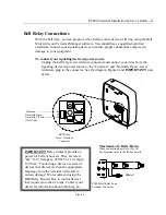
Страница 17: ...screw terminals plug in the connector See the diagram Figure 6 and IMPORTANT note below IMPORTANT Relay contacts provide no power for bells or buzzers They are rated dry for 2 0 amps 24 VDC or 1 0 amp...

Страница 18: ...rminal Setup Mode The terminal must first go through its power up test before you can start the setup mode After the power up test completes the terminal will display All Systems OK To power up the cl...

Страница 19: ...ter The terminal displays ENTER DAY OF WEEK D 1 SUNDAY 7 SATURDAY Enter the number that represents the current day of the week The terminal displays ENTER TIME HH MM Enter the current time and press e...

Страница 20: ...Firmware version of your clock ID Number used to identify your clock MEM Percentage of memory used UPD Identifies the firmware patch version LOAD LIST Ready to be updated from the PayClock software or...

Страница 21: ...when swiping To swipe the badge insert it at the top of the reader then pull it down with a continuous and smooth motion see Figure 8 After the employee has punched the grand totals for the pay period...

Страница 22: ...dge number and press enter Key in the dollar amount Press enter Press enter To see benefit time balances and accumulated hours for the pay period Press Inquiry Swipe your badge or PIN your badge numbe...

Страница 23: ...d date showing on the display Otherwise press exit to resume normal operation To override a lockout zone for an employee In Out punch 1 With the time and date showing press enter swipe your supervisor...

Страница 24: ...relay will close and activate the bell or buzzer for approximately 3 seconds If you press 1 again within 5 seconds the relay will close again This can be repeated as many times as you like Setting up...

Страница 25: ...PC400 Terminal Installation User s Guide 19 A P P E N D I X A Wiring Diagrams RS 232 to Host DB9 RJ45 ADAPTOR...

Страница 26: ...Terminal Block PC400 Terminal Block Note When replacing a PC2000 RS485 terminal with a PC400 you can connect the PC400 terminal using the existing J Kit Simply plug in the cable that goes from the ju...

Страница 27: ...uide 21 A P P E N D I X B PC400 Terminal Block Diagram Modem 10BaseT Connection RS232 RS485 Connection Power Connector Common Normally Open Normally Closed Bell Relay Screw Terminals RS485 Screw Termi...

Страница 28: ...ocket at the U16 location on the circuit board see Figure 10 5 Replace the internal cover plate and install the 4 Philips head screws Do not install the modem cover plate 6 Align the tabs on the back...

Страница 29: ...er s Guide 23 Figure 9 Position the modem module so Pin 1 will be inserted into the bottom socket on the lower right hand corner of the CPU board PC400 Modem Circuit Board Assembly Pin 1 Figure 10 Int...

Страница 30: ...ocation on the circuit board see Figure 11 5 Replace the internal cover plate and install the 4 Philips head screws Do not install the modem cover plate 6 Align the tabs on the back box with slots at...

Страница 31: ...PC400 Terminal Installation User s Guide 25 Figure 11...

Страница 32: ...B9 connector that plugged into the PC2000 Plug the RJ45 adapter cable into the PC400 PC2000 RS485 Plug the existing modular cable into the PC400 terminal Or Bypass the modular junction box and connect...

Страница 33: ...400 Terminal Installation User s Guide 27 Figure 12 Replacing a RS 232 PC2000 with a RS 232 PC400 using the adaptor kit part VIE2787 Replacing PC2000 or PC100R terminals with PC400 s in a RS 485 netwo...

Страница 34: ...ason Your employee swiped the badge in the wrong direction Solution The magnetic stripe should be on the left side of the badge when swiping Insert the badge at the top of the reader and then pull the...

Страница 35: ...the wiring diagram Reason Communication settings for the clock do not match the settings in the software Solution Refer to the section Setup the Clock for setup directions Problem Occasionally a stati...

Страница 36: ...ed with shipping charges prepaid Lathem will not assume any responsibility for any loss or damage incurred in shipping 6 WARRANTY DISCLAIMER AND LIMITATION OF LIABILITY Except only the limited express...

Страница 37: ...2 Connections 7 RS 232 to Host 19 RS 485 Connections 8 RS 485 Network SWIFT 485 Converter 20 S Setting up Supervisor Badges 18 Setup Mode 14 Starting the Terminal Setup Mode 12 Supervisor Override of...

Отзывы: