67
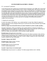
IR POTENTIOMETER ADJUSTMENTS, PWM ONLY:
IR = I (amperage) R (resistance)
The IR potentiometer that is located next to the MAX speed potentiometer on the PWM motor control board
is used to adjust the time it takes the PWM to react to a load or amperage spike. When the user steps onto
the treadbelt a load is introduced to the system which creates an amperage spike. The PWM board senses
this amperage spike and reacts by feeding more power to the drive motor. This “more power” compensates
the amperage spike (load) and the treadmill does not slow down. If the IR was adjusted to react slowly the
user would notice a lag in belt movement when stepping onto the treadbelt. If the IR was adjusted to react
too quickly the user would notice a quick surge when stepping onto the treadbelt. Either way, the treadmill
will surge considerably when this occurs. There have also been isolated cases where the treadmill will
surge without a user walking on it. When this occurs, the red light on the PWM (LED1) will flash in
sequence with the belt surge.
To adjust the IR potentiometer:
No load / belt surging / LED1 flashing = use a small screwdriver to rotate IR pot. Make this adjustment
while the treadmill is running (surging). Rotate the pot in small increments until the treadmill surge subsides
and runs smoothly.
NOTE: the IR pot can be rotated Clockwise or Counter Clockwise to achieve smooth operation.
With load / belt surging / LED1 may be flashing = use a small screwdriver to rotate IR pot. Make this
adjustment while the user is walking on the treadmill. Rotate the pot in small increments until the treadmill
surge subsides and runs smoothly. Keep speed setting under 2.0mph for safety.
NOTE: the IR pot can be rotated CW or CCW to achieve smooth operation.
Possible Cause
: Damaged motor control board.
Disconnect the drive motor from the motor control board. Enter OLS (Open Loop Speed) mode and bring
displayed speed to max. Measure with a voltmeter across the lower motor control board output terminals
A+ and A-. Monitor the DC voltage on your meter. If the DC voltage is surging, the motor control board is
defective. Replace the motor control board.
Symptom: Display reads “SAFE”
Possible Cause
: Safety Lanyard is missing.
Solution: Replace Safety Lanyard.
Possible Cause
: Defective Display Board.
Solution: Replace Display Board.
Symptom: Speed shown is not actual speed.
Possible Cause:
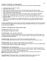
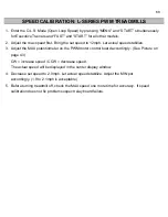
Speed needs to be calibrated. The following page illustrates how to calibrate.
Содержание Cardio Trainer L8
Страница 5: ...5 ...
Страница 27: ...27 Section 3 Parts Identification L8 L9 BED EXPLODED VIEW 18 ...
Страница 28: ...28 L7 BED EXPLODED VIEW L Series Upright ...
Страница 29: ...29 L SERIES UPRIGHT EXPLODED VIEW 112 ...
Страница 30: ...30 L SERIES MOTOR PAN EXPLODED VIEW 111 ...
Страница 35: ...35 COMMERCIAL MOTOR PAN SCR MOTOR CONTROL BOARD ...
Страница 36: ...36 L SERIES 110V COMMERCIAL LOWER WIRE SCHEMATIC ...
Страница 37: ...37 L SERIES 220V COMMERCIAL LOWER WIRE SCHEMATIC ...
Страница 40: ...40 L SERIES SCR UPPER WIRE HARNESS WIRING DIAGRAM ...
Страница 42: ...42 L SERIES HOME MOTOR PAN WIRING SCHEMATIC ...
Страница 47: ...47 L SERIES HOME MOTOR PAN WIRING SCHEMATIC PWM MOTOR CONTROL BOARD W RELAY ASSEMBLY ...
Страница 48: ...48 PWM MOTOR CONTROL BOARD W RELAY ASSEMBLY ...
Страница 49: ...49 L SERIES PWM UPPER WIRE HARNESS WIRING DIAGRAM ...
Страница 50: ...50 EXECUTIVE TRAINER LCD WIRING SCHEMATIC ...
Страница 110: ...110 L SERIES ROAD RUNNER LOWER WIRING DIAGRAM ...
Страница 111: ...111 L SERIES ROAD RUNNER UPPER WIRING SCHEMATIC ...


