115
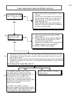
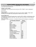
Speed and Grade Diagnostics:
-Hold speed lever in the FAST position and turn key from OFF to PAUSE.
-Belt begins moving at minimum open loop speed.
-Speed and elevation levers function.
-Press TIME to view commanded grade (displays either UP or DOWN).
-Press DISTANCE to view actual grade.
* This is what you view to calibrate the elevation pot.
-Press PACE to view actual open loop speed.
-Press PULSE to view commanded speed.
* Elevation potentiometer setting should read 0.0 @ zero percent grade.
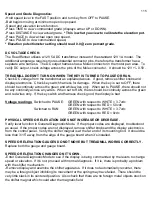
DC VOLTAGE CHECK:
The RoadRunner utilizes a 12V 5A DC transformer instead of the standard 12V 1A model. The
additional amperage requires more substantial connector pins, therefore the transformer has a
separate wire harness. The DC output harness has a Molex connector in the motor pan area. To
verify DC output, check voltage across the pins of the Molex connector. It should be 12V +/- 0.5V.
TREADMILL DOESN’T TURN ON WHEN THE KEY IS TURNED TO PAUSE OR RUN.
Check DC voltage from the transformer as explained above. If good, remove shifter knobs and
display electronics. Check key switch harness for damage. When the key is set to OFF, there
should be continuity across the green and white wires only. When set to PAUSE, there should not
be any continuity across any wires. When set to RUN, there should be continuity across the green
and red wires only. If the key switch and harness check good, the display is bad.
Voltage readings:
Switched to PAUSE:
GREEN with respect to WHITE = 3.7vdc
GREEN with respect to RED = 5.0vdc
Switched to RUN
GREEN with respect to WHITE = 3.7vdc
GREEN with respect to RED = 0vdc
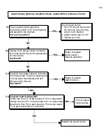
PHYSICAL SPEED OR ELEVATION DOES NOT INCREASE OR DECREASE.
Verify lever function in General Diagnostic Mode. If the proper codes are displayed, troubleshoot
as usual. If the proper codes are not displayed, remove shifter knobs and the display electronics
from the control panel. Verify the shifter magnet is at the far end of its mounting bolt. It should be
less than 3/15” away from the edge of the gauge board when it’s installed.
SPEED OR ELEVATION GAUGES DO NOT MOVE BUT TREADMILL WORKS CORRECTLY.
Replace both the gauge and gauge board.
SPEED OR ELEVATION CHANGES ON IT’S OWN.
-Enter General Diagnostic Mode to see if the display is being commanded by the levers to change
speed or elevation. If it’s not, proceed with normal diagnosis. If it is, there is probably a problem
with the shifter mechanism.
-Remove display and examine the shifter apparatus. If it does not automatically recenter, there
may be a foreign object inhibiting its movement or the spring may have failed. There should be
very little slack in its centered position. Also check that there are no foreign metal objects stuck on
the shifter magnet which could alter the magnetic field.
Содержание Cardio Trainer L8
Страница 5: ...5 ...
Страница 27: ...27 Section 3 Parts Identification L8 L9 BED EXPLODED VIEW 18 ...
Страница 28: ...28 L7 BED EXPLODED VIEW L Series Upright ...
Страница 29: ...29 L SERIES UPRIGHT EXPLODED VIEW 112 ...
Страница 30: ...30 L SERIES MOTOR PAN EXPLODED VIEW 111 ...
Страница 35: ...35 COMMERCIAL MOTOR PAN SCR MOTOR CONTROL BOARD ...
Страница 36: ...36 L SERIES 110V COMMERCIAL LOWER WIRE SCHEMATIC ...
Страница 37: ...37 L SERIES 220V COMMERCIAL LOWER WIRE SCHEMATIC ...
Страница 40: ...40 L SERIES SCR UPPER WIRE HARNESS WIRING DIAGRAM ...
Страница 42: ...42 L SERIES HOME MOTOR PAN WIRING SCHEMATIC ...
Страница 47: ...47 L SERIES HOME MOTOR PAN WIRING SCHEMATIC PWM MOTOR CONTROL BOARD W RELAY ASSEMBLY ...
Страница 48: ...48 PWM MOTOR CONTROL BOARD W RELAY ASSEMBLY ...
Страница 49: ...49 L SERIES PWM UPPER WIRE HARNESS WIRING DIAGRAM ...
Страница 50: ...50 EXECUTIVE TRAINER LCD WIRING SCHEMATIC ...
Страница 110: ...110 L SERIES ROAD RUNNER LOWER WIRING DIAGRAM ...
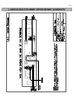
Страница 111: ...111 L SERIES ROAD RUNNER UPPER WIRING SCHEMATIC ...


