39
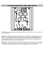
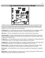
SPD (yellow)
– The SPD LED flashes on and off (relative to speed) when the speed sensor is
operating properly.
GRD (red)
– The GRD (GRADE) LED should
NEVER
come on. It illuminates only when the elevation
potentiometer becomes out of calibration.
SERIAL (red
) – The SERIAL LED should
NEVER
come on. It illuminates only when there is an interruption
of the flow of data between the upper and lower boards. This could be a loose or pushed pin on the main
wire harness.
+5V (green)
– The +5V light comes on when there is power going to the Upper Display. If the light is not
on check wire harness for connections. If it is not the wire harness then the MCB is defective.
Содержание Cardio Trainer L8
Страница 5: ...5 ...
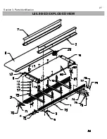
Страница 27: ...27 Section 3 Parts Identification L8 L9 BED EXPLODED VIEW 18 ...
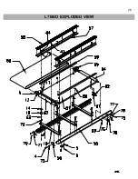
Страница 28: ...28 L7 BED EXPLODED VIEW L Series Upright ...
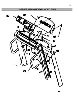
Страница 29: ...29 L SERIES UPRIGHT EXPLODED VIEW 112 ...
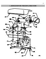
Страница 30: ...30 L SERIES MOTOR PAN EXPLODED VIEW 111 ...
Страница 35: ...35 COMMERCIAL MOTOR PAN SCR MOTOR CONTROL BOARD ...
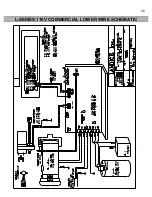
Страница 36: ...36 L SERIES 110V COMMERCIAL LOWER WIRE SCHEMATIC ...
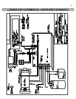
Страница 37: ...37 L SERIES 220V COMMERCIAL LOWER WIRE SCHEMATIC ...
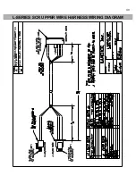
Страница 40: ...40 L SERIES SCR UPPER WIRE HARNESS WIRING DIAGRAM ...
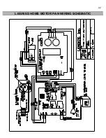
Страница 42: ...42 L SERIES HOME MOTOR PAN WIRING SCHEMATIC ...
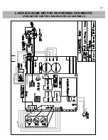
Страница 47: ...47 L SERIES HOME MOTOR PAN WIRING SCHEMATIC PWM MOTOR CONTROL BOARD W RELAY ASSEMBLY ...
Страница 48: ...48 PWM MOTOR CONTROL BOARD W RELAY ASSEMBLY ...
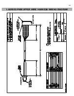
Страница 49: ...49 L SERIES PWM UPPER WIRE HARNESS WIRING DIAGRAM ...
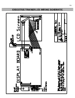
Страница 50: ...50 EXECUTIVE TRAINER LCD WIRING SCHEMATIC ...
Страница 110: ...110 L SERIES ROAD RUNNER LOWER WIRING DIAGRAM ...
Страница 111: ...111 L SERIES ROAD RUNNER UPPER WIRING SCHEMATIC ...

