77
DISPLAY CONTROL PACKAGE (DCP) INSTALLATION
1.
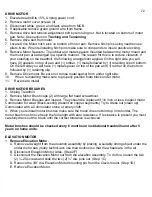
Attach Heart Rate Control (HRC) module and bracket
assembly to left upright leg. You will need to remove the
control panel attachment screw in order to mount bracket.
Next route the Pulse Bracket through the end cap bracket and reassemble it to the treadmill.
2.
The HRC wire harness needs to be routed between the end cap
bracket and control panel frame. Remove the control panel end cap
bracket in order to properly route this harness. There is a notch in
control panel frame for harness to pass through.
3.
Install the DCP control panel assembly into the control
panel frame.
4.
Insert upper wire harness (located on the right hand side
upright) into the display board. The harness connection has a
locking clip designed to keep the harness connection tight.
Make sure this clip is locked into place.
5
Secure upper wire harness to upright leg. The harness
snaps intotwo “J-clips” mounted to the upright leg.
6.
Refer to your owner’s manual for remaining assembly instructions.
Two bracket screws
Harness to display
J-CLIP #1
J-CLIP #2
Содержание Cardio Trainer L8
Страница 5: ...5 ...
Страница 27: ...27 Section 3 Parts Identification L8 L9 BED EXPLODED VIEW 18 ...
Страница 28: ...28 L7 BED EXPLODED VIEW L Series Upright ...
Страница 29: ...29 L SERIES UPRIGHT EXPLODED VIEW 112 ...
Страница 30: ...30 L SERIES MOTOR PAN EXPLODED VIEW 111 ...
Страница 35: ...35 COMMERCIAL MOTOR PAN SCR MOTOR CONTROL BOARD ...
Страница 36: ...36 L SERIES 110V COMMERCIAL LOWER WIRE SCHEMATIC ...
Страница 37: ...37 L SERIES 220V COMMERCIAL LOWER WIRE SCHEMATIC ...
Страница 40: ...40 L SERIES SCR UPPER WIRE HARNESS WIRING DIAGRAM ...
Страница 42: ...42 L SERIES HOME MOTOR PAN WIRING SCHEMATIC ...
Страница 47: ...47 L SERIES HOME MOTOR PAN WIRING SCHEMATIC PWM MOTOR CONTROL BOARD W RELAY ASSEMBLY ...
Страница 48: ...48 PWM MOTOR CONTROL BOARD W RELAY ASSEMBLY ...
Страница 49: ...49 L SERIES PWM UPPER WIRE HARNESS WIRING DIAGRAM ...
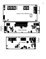
Страница 50: ...50 EXECUTIVE TRAINER LCD WIRING SCHEMATIC ...
Страница 110: ...110 L SERIES ROAD RUNNER LOWER WIRING DIAGRAM ...
Страница 111: ...111 L SERIES ROAD RUNNER UPPER WIRING SCHEMATIC ...

