23
How to Install
ASSEMBLY INSTRUCTIONS
STEP 1
Lay the treadmill on the ground.
Using a razor blade knife cut the box just
above the brass staples along all sides of the
box.
DO NOT
cut through the center of the box, as
you could hit the treadmill.
Remove the box and discard.
STEP 2
The treadmill components are held together
with plastic strapping.
Carefully cut and remove the strapping and
remove the treadmill from the pallet.
Carefully remove the upright side cover from
the upright assembly.
STEP 3 Mount the upright
Slide the upright down onto the 8 side frame
bolts. Be sure the washers are located on the
outside of the upright and against the head of
the bolt. Tighten bolts with a 3/8” extended
socket.
•
For L8 models insert and tighten the top
frame bolts. (These bolts can be found in the
hardware kit)
STEP 4 Snap side cover into
place
Carefully align the side frame cover. Working
from top to bottom, snap the upright side
cover into place.
Содержание Cardio Trainer L8
Страница 5: ...5 ...
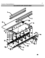
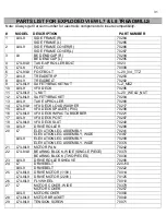
Страница 27: ...27 Section 3 Parts Identification L8 L9 BED EXPLODED VIEW 18 ...
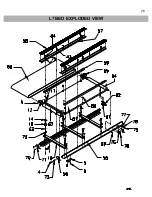
Страница 28: ...28 L7 BED EXPLODED VIEW L Series Upright ...
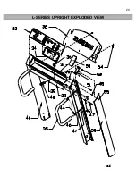
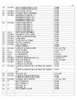
Страница 29: ...29 L SERIES UPRIGHT EXPLODED VIEW 112 ...
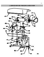
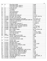
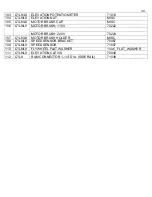
Страница 30: ...30 L SERIES MOTOR PAN EXPLODED VIEW 111 ...
Страница 35: ...35 COMMERCIAL MOTOR PAN SCR MOTOR CONTROL BOARD ...
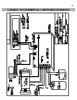
Страница 36: ...36 L SERIES 110V COMMERCIAL LOWER WIRE SCHEMATIC ...
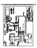
Страница 37: ...37 L SERIES 220V COMMERCIAL LOWER WIRE SCHEMATIC ...
Страница 40: ...40 L SERIES SCR UPPER WIRE HARNESS WIRING DIAGRAM ...
Страница 42: ...42 L SERIES HOME MOTOR PAN WIRING SCHEMATIC ...
Страница 47: ...47 L SERIES HOME MOTOR PAN WIRING SCHEMATIC PWM MOTOR CONTROL BOARD W RELAY ASSEMBLY ...
Страница 48: ...48 PWM MOTOR CONTROL BOARD W RELAY ASSEMBLY ...
Страница 49: ...49 L SERIES PWM UPPER WIRE HARNESS WIRING DIAGRAM ...
Страница 50: ...50 EXECUTIVE TRAINER LCD WIRING SCHEMATIC ...
Страница 110: ...110 L SERIES ROAD RUNNER LOWER WIRING DIAGRAM ...
Страница 111: ...111 L SERIES ROAD RUNNER UPPER WIRING SCHEMATIC ...


