AA02A.C01
Service instruction POP-I
Page 7/7
Executed by: HL/CML
Issued on: 11 december. 2002
Accepted by: SL
Rev. date: 12 March 2021
Please Note
End cover, oil chamber and gear must be turned
anti-clockwise
as much as possible, seen from the end of the
propeller, in order to balance the space in the bolt holes before the final tightening of the bolts.
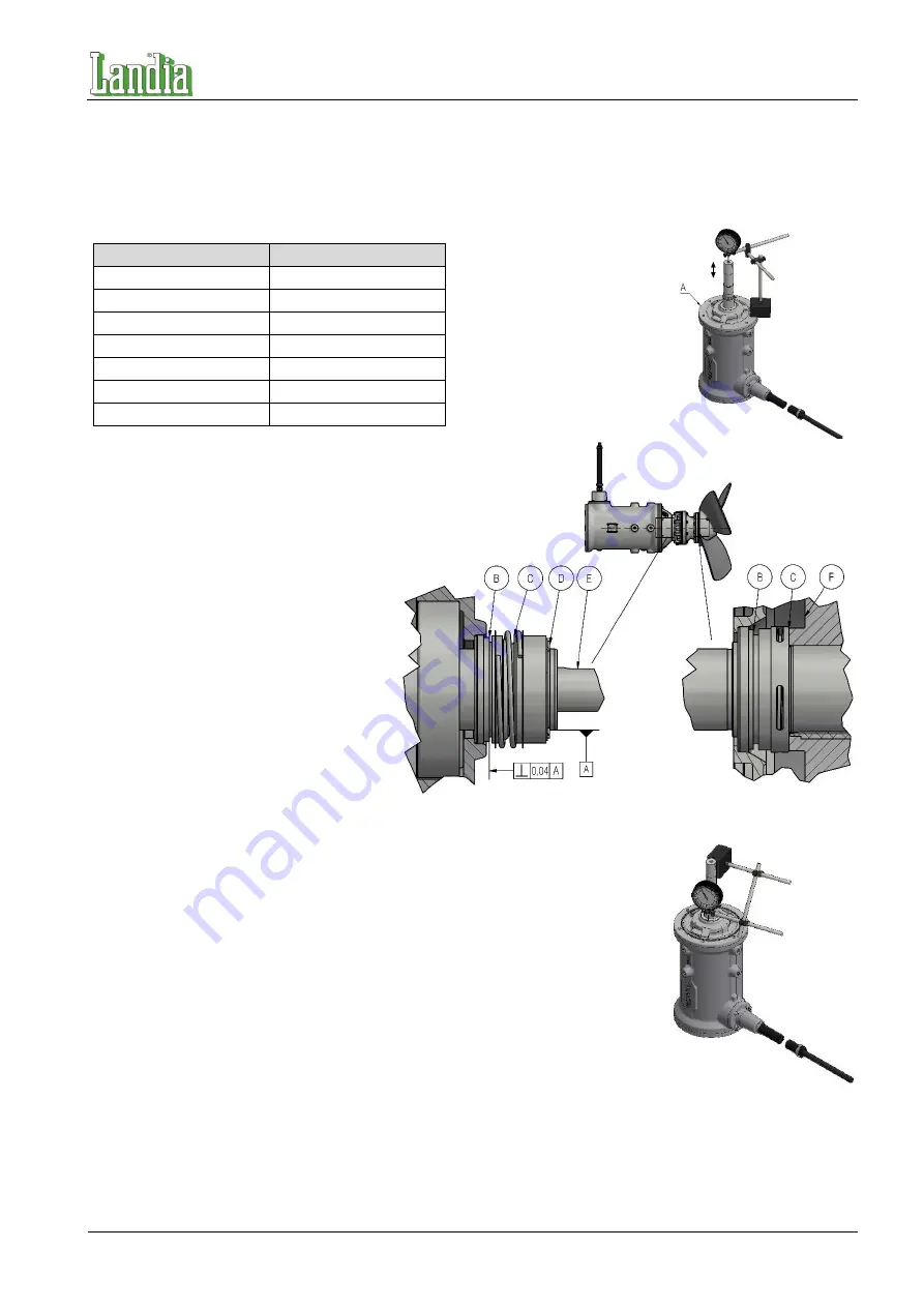
After installing the bearing flange control the axial space as stated in the table below.
Motor series (ms.)
Acceptable margin
ms80
0.7 ± 0.05 mm
ms90
0.7 ± 0.05 mm
ms100
0.9 ± 0.05 mm
ms112
1.0 ± 0.05 mm
ms132
1.0 ± 0.05 mm
ms160
1.1 ± 0.05 mm
ms180
1.5 ± 0.05 mm
Installation of mechanical shaft seals
When installing the mechanical shaft seals,
please be aware that these are precision
products and that they should be handled
as such. The slide faces must be protected
during the installation.
Push the stationary sealing ring into place.
Be careful not to damage the slide face
during the installation.
B. Stationary sealing part
C. Rotating sealing part
D. Locking ring
E. Shaft
F. Propeller hub
Push the stationary sealing part, pos. B,
into place. Be careful not to damage the
slide face during the installation.
When the stationary part is mounted and
straightened with a dial gauge, wipe it off with degreaser.
The rotating sealing ring is put over the shaft. To ease the installation put soap
water on the interior side of the rubber bellows as well as on the shaft. Do not apply
silicone, PTFE lubricants or oil as they will prevent the rubber bellows from sticking
to the shaft. Installation arbour should be used.
The propeller hub keeps the outer mechanical shaft seal in place. This happens
when the propeller hub is tightened against the output shaft collar. At the inner
mechanical shaft seal the locking ring must be put on the shaft and the seal pressed
together until the locking ring snaps into the locking ring groove. Inspect the sealing
by turning the motor shaft.
Test the mixer for leakage by submerging it and by putting the motor casing and
the oil chamber under pressure. The pressure is to be approx. 1 bar. Leakage (air
bubbles) must not appear. Oil is filled into the oil chamber/gear. During the filling,
the mixer must be in a horizontal position.
Oil quantity: see spare parts list.
Repair of surface coating, if any, is necessary prior to operation start. See instruction for maintenance of surface
coating.
We reserve the right to technical alterations Translated from Danish.
A. Bearing flange
Содержание POP-1
Страница 18: ...0 1 2 3 4 2 0 0 1 0 0 1 1 0 1 1 0 2 3 4 5 6 7 4 8 9 4 7 5 6 7...
Страница 84: ......


