AXE 3 D
17
EN
cod. 3540Z230 - 01/2011 (Rev. 00)
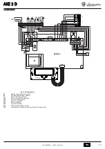
5.4 Wiring diagram
fig. 21 - Wiring diagram
32
Heating circulating pump (optional)
42
DHW temperature probe (optional)
72
Room thermostat (optional)
130
DHW circulating pump (optional)
138
External probe (optional)
139
Room unit (optional)
211
Burner connector
246
Pressure transducer
278
Double sensor (h safety)
304
2nd stage burner connector (version with 6 and 7 elements only)
DBM06C
T° T°
278
OUT
+5V
GND
246
L
N
4
5
6
7
8
9 10 11 12 13 14 15 16 17 18
L
N
230V
50Hz
32
138
139
72
211
304
130
42
DSP08
X9

