www..lairdconnect.com/wireless
17
© Copyright 2020 Laird Connectivity. All Rights Reserved
Americas
: +1-800-492-2320
Europe
: +44-1628-858-940
Hong Kong
: +852 2923 0610
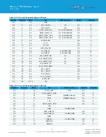
Header
Position
M2.#
Net
DVK Function
Switch
Position
P3
15
15
P1.04
LED1 BLUE
S3
2
P3
16
17
P1.05
LED2 GREEN
S3
3
P3
17
19
P1.06
LED3 RED
S3
4
P3
18
21
P1.07
LED4 GREEN
S3
5
P3
19
23
P0.04_AIN2
S3
6
P3
20
33
GND
P3
21
35
P1.12_GPIO6
S3
7
P3
22
37
SIM_RST
S3
8
39
GND
P3
23
41
P1.01
S3
9
P3
24
43
P1.08_GPIO2
S3
10
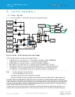
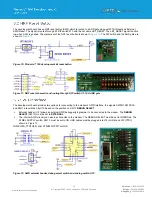
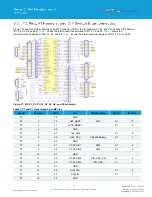
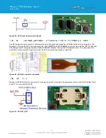
The 4-wire UART connections on the Pinnacle
™ 100 modem and the FTDI IC are shown in
. The UART connections
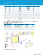
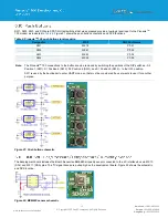
schematic shown in Figure 18, and DVK locations shown in Figure 19
Table 4: UART connections
Pinnacle
™ 100 M2 & U5
Pinnacle
™ 100 Default Function
FTDI IC UART
J12
M2.38, P0.07, U5 pin 32
HOST_UART_RTS (output)
USB_RTS
6
M2.36, P0.05, U5 pin 8)
HOST_UART_CTS (input)
USB_CTS
2
M2.34, P0.08, (U5 pin 30)
HOST_UART_TX (output)
USB_TX
4
M2.32, P0.06, (U5 pin 2)
HOST_UART_RX (input)
USB_RX
5
Figure 18: UART connections schematic
Содержание 453-00010-K1
Страница 1: ...Version 1 0 ...


