www..lairdconnect.com/wireless
18
© Copyright 2020 Laird Connectivity. All Rights Reserved
Americas
: +1-800-492-2320
Europe
: +44-1628-858-940
Hong Kong
: +852 2923 0610
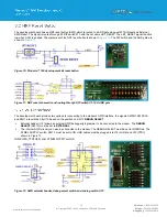
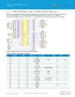
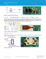
Figure 19: J30 FTDI USB and J12
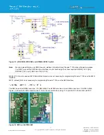
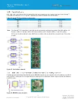
The development board includes six indicator LEDs. Four LEDs (
LED1
– LED4
) are for development use and are connected
to the Pinnacle
TM
The Schematic and location are shown in Figure 20
Table 5: Pinnacle
TM
100 DVK LEDs and signal mapping
Designator
Color
NRF Port Name
LED1
Blue
P1.04
LED2
Green
P1.05
LED3
Red
P1.06
LED4
Green
P1.07
Note:
The Pinnacle
TM
100 connections to the LEDs can be removed by switching positions 2, 3, 4, and 5 of S3 to the OFF
position.
LED4 indicate the status of the bootloader.
LED5
(Red)
‘ON’ indicates the ATMEL SUPPLY switch is set to OFF.
LED6
(Green)
‘ON’ indicates Internal SWD activity.
Figure 20: LEDs schematic
Содержание 453-00010-K1
Страница 1: ...Version 1 0 ...

