background image

2K8

2-1-16

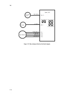
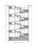
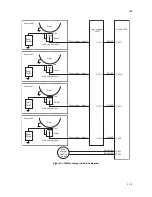
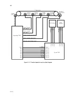
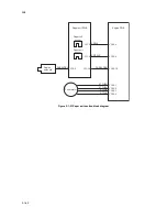
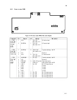
Figure 2-1-17 Transfer/separation section block diagram

Engine PWB

High voltage PWB

Left ID sensor

Right

ID sensor

Secondary
transfer roller

Primary
transfer
roller M

Primary
transfer
roller C

Primary
transfer
roller Y

Primary
transfer
roller K

Transfer belt

Cleaning
roller

T2RREMN

Secondary transfer bias output

Primary transfer bias output K

Primary transfer bias output Y

Primary transfer
bias output C

Primary transfer
bias output M

Cleaning bias output

YC16-7

VOSL

VOPL

LEDREFL

VOSR

VOPR

LEDREFR

YC5-5

YC5-4

YC5-2

YC6-5

YC6-4

YC6-2

CN1-21

CLCNT

YC16-20

CN1-8

T1MCNT

YC16-21

CN1-7

T1CCNT

YC16-22

CN1-6

T1YCNT

YC16-23

CN1-5

T1KCNT

YC16-24

CN1-4

T2CNT

YC16-25

CN1-3

Содержание ECOSYS FS-C5350DN

Страница 1: ...SERVICE MANUAL Published in December 2009 2K8SM061 Rev 1 FS C5350DN...

Страница 2: ...icials for details in your area for proper disposal ATTENTION IL Y A UN RISQUE D EXPLOSION SI LA BATTERIE EST REMPLACEE PAR UN MODELE DE TYPE INCORRECT METTRE AU REBUT LES BATTERIES UTILISEES SELON LE...

Страница 3: ...Revision history Revision Date Replaced pages Remarks 1 December 11 2009 1 4 19 1 4 20 1 5 2...

Страница 4: ...This page is intentionally left blank...

Страница 5: ...sonnel to ensure the safety of their customers their machines as well as themselves during maintenance activities Service personnel are advised to read this booklet carefully to familiarize themselves...

Страница 6: ...this symbol CAUTION Bodily injury or damage to property may result from insufficient attention to or incorrect compliance with warning messages using this symbol Symbols The triangle symbol indicates...

Страница 7: ...or dusty place This may cause fire or electric shock Do not install the copier near a radiator heater other heat source or near flammable material This may cause fire Allow sufficient space around the...

Страница 8: ...carefully Always check that the copier is correctly connected to an outlet with a ground connection Check that the power cable covering is free of damage Check that the power plug is dust free If it i...

Страница 9: ...trapped wire and missing screws Check that all the caution labels that should be present on the machine according to the instruction handbook are clean and not peeling Replace with new ones if necess...

Страница 10: ...This page is intentionally left blank...

Страница 11: ...ely white 1 4 22 2 No image appears entirely black 1 4 23 3 A specific color is printed solid 1 4 23 4 The back side gets dirty 1 4 23 5 Image is too light 1 4 24 6 The background is colored 1 4 24 7...

Страница 12: ...ltage PWB 1 5 34 1 5 9 Others 1 5 37 1 Detaching and refitting the laser scanner unit 1 5 37 2 Detaching and refitting the ozone filter 1 5 39 3 Direction of installing the principal fan motors 1 5 40...

Страница 13: ...2K8 2 4 Appendixes 2 4 1 Appendixes 2 4 1 1 Wiring diagram 2 4 1 2 Repetitive defects gauge 2 4 3 3 Maintenance parts list 2 4 4...

Страница 14: ...2K8 This page is intentionally left blank...

Страница 15: ...the printing speed becomes 14 ppm Letter 28 ppm Legal 23 ppm Duplex printing speed A4 30 ppm B5 A5 27 ppm After 16 pages the printing speed becomes 14 ppm Letter 32 ppm Legal 13 ppm First print out t...

Страница 16: ...Hz 60 Hz max 4 7 A European countries Max Allowable voltage fluctuation 10 Max Allowable frequency fluctuation 2 Power consumption 120 V AC model Maximum 1 104 W or less During printing 517 W During s...

Страница 17: ...4 Paper stopper 5 MP tray 6 Cassette 7 Power switch 8 Left cover 9 Waste toner box 10 Main charger units 11 Toner container M 12 Toner container C 13 Toner container Y 14 Toner container K 15 Duplex...

Страница 18: ...2K8 1 1 4 2 Operation panel Figure 1 1 2 1 2 3 5 5 5 6 9 4 5 7 8 1 Message display 2 Ready indicator 3 Data indicator 4 Attention indicator 5 Arrow keys 6 MENU key 7 OK key 8 GO key 9 CANCEL key...

Страница 19: ...m unit Y 7 Drum unit K 8 Main charger unit M 9 Main charger unit C 10 Main charger unit Y 11 Main charger unit K 12 Laser scanner unit MC 13 Laser scanner unit YK 14 Developing unit M 15 Developing un...

Страница 20: ...2K8 1 1 6 This page is intentionally left blank...

Страница 21: ...low humidity an abrupt change in the environmental temperature and cool or hot direct air Avoid places subject to dust and vibrations Choose a surface capable of supporting the weight of the machine...

Страница 22: ...ner container Black 4 Toner container Cyan 5 Toner container Magenta 6 Waste toner box 7 Power cord 8 Main pad 9 Bottom pad 10 Bottom front side pad 11 Outer case 12 Top pad 13 Top tray 14 Top spacer...

Страница 23: ...container Cyan 5 Toner container Magenta 6 Waste toner box 7 Power cord 8 Document tray 9 Upper left cushion 10 Upper right cushion 11 Outer case 12 Machine cover 600 600 900 13 Cassette cushion 14 D...

Страница 24: ...2 4 2 Removing the tape Procedure 1 Remove the tape A 2 Remove two tapes B and then remove the installation guide and desiccating agent Figure 1 2 4 Tape A Tape B Tape B Desiccating agent Installation...

Страница 25: ...5 3 Insert the expansion memory modules into the expansion memory socket so that the notches on the memory align with the corre sponding protrusions in the slot 4 Refit the main PWB 5 Print a status...

Страница 26: ...y card while printer power is on Doing so may cause damage to the printer and the memory card 2 Remove the two screws and then remove the main PWB Figure 1 2 7 3 Insert the memory card into the memory...

Страница 27: ...ter power is on Doing so may cause damage to the printer and the hard disk 2 Remove two screws and then remove the option interface slot cover 3 Insert the hard disk into the option interface slot Pus...

Страница 28: ...2K8 1 2 8 This page is intentionally left blank...

Страница 29: ...int a network status page To print a test page Write Data To write data into a USB memory To reset the counter after replacing the maintenance kit To perform developing unit refreshing To perform LSU...

Страница 30: ...mware Version 2K8_3000 000 040 1 Memory Status Standard Size Option Slot Total Size Controller Information 2009 05 27 XXXXXXXX XXXXXXXX XXXXXXXX XXXXXXXX XXXXXXXXXXXXXXXX 500 0 kB 500 0 kB 1000 0 kB T...

Страница 31: ...se Multi purpose feeder Not Installed Absence Presence or absence of the paper feeder 4 Installed Paper feeder Normal Installed Multi purpose Multi purpose feeder Not Installed Absence Presence or abs...

Страница 32: ...00 0000000000000000 0000000000000000 0000000000000000 0000000000000000 0000000000000000 0000000000000000 0000000000000000 0000000000000000 0000000000000000 0000000000000000 0000000000000000 0000000000...

Страница 33: ...Left offset for each paper source MP tray Paper feeder 1 Paper feeder 2 Paper feeder 3 Duplex Page rotation L value settings Top margin integer Top margin decimal place Left margin integer Left margin...

Страница 34: ...5 Heavy 2 6 Heavy 3 7 Extra Heavy Fuser settings 0 High 1 Middle 2 Low 3 Vellum Duplex settings 0 Disable 1 Enable SPD information Calibration information Calibration information Calibration informati...

Страница 35: ...ptional font version Optional table version Optional message version WEB option version Color table version Drum unit ID Black Cyan Magenta Yellow Drum unit serial number Black Cyan Magenta Yellow NOT...

Страница 36: ...m units of four colors Procedure 1 Enter the service mode Print Test Page 2 Press the OK key Print Test Page will be displayed 3 Press the OK key A sheet of test page will be printed Completion 1 Sinc...

Страница 37: ...it Paper feed roller assembly Retard roller assembly Ozone filter Purpose To reset the life counter for the drum units developing units intermediate transfer unit and fuser unit included in maintenanc...

Страница 38: ...sor keys 6 digit data is assigned on a label attached to the package or developing unit 4 Press the OK key OK 128F1E will be displayed 5 Press the OK key DEV SET will be displayed The initial value 6...

Страница 39: ...e data LSU dust shield glass and main charger cleaning Description The LSU cleaning motor drives the cleaning pad which in turn wipes clean the LSU dust shield glass The main charger cleaning motor dr...

Страница 40: ...um unit scrapes toner off the drum surface to clean it Purpose To clean the drum surface when image failure occurs due to the drum This mode is effective when dew condensation on the drum occurs Metho...

Страница 41: ...on analysis based on the frequency of paper misfeeds self diag nostic errors and replacements Procedure 1 Connect the USB or network cable between printer and PC network 2 Connect the power cord Figur...

Страница 42: ...3 T04 T05 10 20 30 40 50 999 Counter Log Event Descriptions 10 01 88 01 01 10 01 88 01 01 10 01 88 01 01 10 01 88 01 01 10 01 88 01 01 10 01 88 01 01 10 01 88 01 01 10 01 88 01 01 10 01 88 01 01 10 01...

Страница 43: ...not arrive at the paper feeder 1 s PF paper feed sensor 2 Paper feeder 1 30 Paper does not arrive at the paper feeder 1 s PF paper feed sensor 3 Paper feeder 2 30 Paper does not arrive at the paper fe...

Страница 44: ...Jam location Figure 1 3 7 Registration sensor Paper exit sensor Duplex conveying sensor Paper full sensor PF paper feed sensor Sensors MP tray Cassette 1 printer Paper feeder 1 Paper feeder 2 Paper f...

Страница 45: ...R A8 16K E 32 Statement R B2 Statement E 33 Folio 34 Western type 2 35 Western type 4 d Detail of paper type Hexadecimal 01 Plain 02 Transparency 03 Preprint 04 Labels 05 Bond 06 Recycle 07 Vellum 08...

Страница 46: ...detection If the occurrence of the previous unknown toner detection is less than 5 all of the unknown toner detection are logged The total page count at the time of the Toner Empty error with using an...

Страница 47: ...he component where the paper jam has occurred is also indicated The printer auto matically goes off line when this message is displayed Remove jammed paper After removing jammed paper the printer will...

Страница 48: ...y an error message on the operation panel An error message consists of a message prompting a contact to service personnel total print count and a four digit error code indicating the type of the error...

Страница 49: ...PWB YC3 YC5 and paper feeder interface connec tor or improper connector inser tion Reinsert the connector Also check for conti nuity within the connector harness If none remedy or replace the harness...

Страница 50: ...ection signal is detected continuously for 50 times 5 s at 100 ms intervals After the PF lift motor is driven the ON status of PF lift limit sensor cannot be detected for 8 seconds The cassette instal...

Страница 51: ...paper feeder Defective engine PWB Replace the engine PWB See page 1 5 29 1510 1530 1550 PF warm air heater side blower high temperature error Option paper feeder A temperature higher than 85 C 185 F i...

Страница 52: ...harness between PF ther mistor 2 and PF main PWB YC12 or improper con nector insertion Reinsert the connector Also check for conti nuity within the connector harness If none remedy or replace the har...

Страница 53: ...ess between PF ther mistor 2 and PF main PWB YC12 or improper con nector insertion Reinsert the connector Also check for conti nuity within the connector harness If none remedy or replace the harness...

Страница 54: ...r insertion Reinsert the connector Also check for conti nuity within the connector harness If none remedy or replace the harness Defective drive transmission sys tem of the main charger cleaning motor...

Страница 55: ...loping motor K turns on Defective harness between develop ing motor K and engine PWB YC26 or improper connec tor insertion Reinsert the connector Also check for conti nuity within the connector harnes...

Страница 56: ...gine PWB Replace the engine PWB See page 1 5 29 4202 Laser output error Cyan The pin photo signal PDN is not output from PD PWB C for one second while laser is emitted Defective harness between APC PW...

Страница 57: ...s Defective harness between LSU cleaning motor and engine PWB YC37 or improper connec tor insertion Reinsert the connector Also check for conti nuity within the connector harness If none remedy or rep...

Страница 58: ...tor Also check for conti nuity within the connector harness If none remedy or replace the harness Defective harness between drum relay PWB YC1 and engine PWB YC34 or improper connec tor insertion Rein...

Страница 59: ...40 seconds in warming up The detected temperature of fuser ther mistor does not reach the specified tem perature ready indication temperature after fuser heater lamp has been turned on continuously fo...

Страница 60: ...c tor insertion Reinsert the connector Also check for conti nuity within the connector harness If none remedy or replace the harness Broken fuser ther mistor wire Replace the fuser unit See page 1 5 2...

Страница 61: ...tion Reinsert the connector Also check for conti nuity within the connector harness If none remedy or replace the harness Defective drive transmission system of the toner motor C Check if the gears ro...

Страница 62: ...elay PWB and reinstall them if necessary See page 1 5 14 Defective harness between drum relay PWB YC1 and engine PWB YC34 or improper connec tor insertion Reinsert the connector Also check for conti n...

Страница 63: ...m if necessary See page 1 5 12 Defective harness between drum relay PWB YC1 and engine PWB YC34 or improper connec tor insertion Reinsert the connector Also check for conti nuity within the connector...

Страница 64: ...page 1 5 14 Defective engine PWB Replace the engine PWB See page 1 5 29 7413 Drum unit M non installing error The EEPROM of drum PWB M does not communicate normally Incompatible drum unit M is instal...

Страница 65: ...ne operates properly by reverting the engine controller and the drum unit to the old ones To replace the engine PWB and the drum unit at the same time turn on the printer after replacing either one Ch...

Страница 66: ...e error is not resolved replace main PWB See page 1 5 28 Defective engine PWB Replace engine PWB See page 1 5 29 F050 Engine PWB ROM checksum error Some error may have occurred when downloading the fi...

Страница 67: ...White streaks are printed vertically 8 Black streaks are printed vertically 9 Streaks are printed horizontally 10 Spots are printed See page 1 4 24 See page 1 4 25 See page 1 4 25 See page 1 4 25 See...

Страница 68: ...ee page 1 5 37 Defective engine PWB Replace the engine PWB See page 1 5 29 No develop ing bias output Defective harness between high voltage PWB and engine PWB YC16 or improper con nector insertion Re...

Страница 69: ...all colors Defective laser scanner unit Replace the laser scanner unit YK and laser scanner unit MC See page 1 5 37 Print example Causes Check procedures corrective measures Defective main charger un...

Страница 70: ...uesting toner replenish ment replace the container Insufficient agitation of toner con tainer Shake the toner container vertically approximately 10 times Paper damp Check the paper storage conditions...

Страница 71: ...worn cleaning blade in the drum unit Replace the drum unit See page 1 5 14 Worn primary transfer belt Replace the intermediate transfer unit See page 1 5 16 Dirty main charger wire Perform the main c...

Страница 72: ...in the drum unit Replace the drum unit Defective intermediate transfer belt cleaning Replace the intermediate transfer unit See page 1 5 16 Defective fuser unit Replace the fuser unit See page 1 5 25...

Страница 73: ...paper Flawed heat roller or press roller Replace the fuser unit See page 1 5 25 Print example Causes Check procedures corrective measures Defective calibration Perform the color calibration Refer to o...

Страница 74: ...so check for continuity within the con nector harness If none remedy or replace the harness Power source fan motor Engine PWB YC8 Ozone fan motor Engine PWB YC11 Developing fan motor 1 Engine PWB YC10...

Страница 75: ...engine PWB See page 1 5 29 Broken paper sensor 1 2 actuator Check the bending of the actuator lever of the paper sensor 1 2 if there is trouble remedy or replace Defective engine PWB Replace the engin...

Страница 76: ...tive interlock switch Replace the interlock switch Defective engine PWB Replace the engine PWB See page 1 5 29 15 The message requesting left cover to be closed is dis played when the left cover is cl...

Страница 77: ...he slider visually and correct or replace if necessary Deformed MP tray slider Check visually and replace any deformed slider 4 Multiple sheets of paper are fed at one time Check if the paper is curle...

Страница 78: ...2K8 1 4 32 This page is intentionally left blank...

Страница 79: ...ke care not to get the wire caught To reassemble the parts use the original screws If the types and the sizes of screws are not known refer to the PARTS LIST 2 Drum Note the following when handling or...

Страница 80: ...A black colored band when seen through the left side window A shiny or gold colored band when seen through the right side window The above will reveal that the toner container is a genuine Kyocera Mit...

Страница 81: ...overs 1 Detaching and refitting the left rear cover left upper cover and left front cover Procedure 1 Open the left cover 2 Remove the waste toner box 3 Remove two screws Figure 1 5 3 Left cover Waste...

Страница 82: ...2K8 1 5 4 4 Open the top cover 5 Release the five hooks and then remove the left rear cover Figure 1 5 4 Hooks Hooks Left rear cover Left rear cover Top cover...

Страница 83: ...1 5 5 6 Open the front cover 7 Remove the screw and then remove the left upper cover 8 Slide the left front cover upward and then remove it Figure 1 5 5 Screw Left front cover Front cover Left upper c...

Страница 84: ...ht upper cover and right front cover Procedure 1 Open the top cover 2 Open the right cover 3 Remove the two screws 4 Release the five hooks and then remove the right rear cover Figure 1 5 6 Screw Scre...

Страница 85: ...5 7 5 Open the front cover 6 Remove the two screws and then remove the right upper cover 7 Slide the right front cover and then remove it Figure 1 5 7 Right front cover Front cover Right upper cover S...

Страница 86: ...2K8 1 5 8 1 5 3 Paper feed section 1 Detaching and refitting the paper feed roller assembly paper feed roller and pickup roller Procedure 1 Remove the cassette Figure 1 5 8 Cassette...

Страница 87: ...ile pressing the lever B and then remove the paper feed roller assembly Figure 1 5 9 4 Check or replace the paper feed roller assembly and refit all the removed parts Figure 1 5 10 Paper feed roller a...

Страница 88: ...elease the two hooks and then remove the retard guide retard roller assembly Figure 1 5 11 3 Remove the retard roller assembly 4 Check or replace the retard roller assembly and refit all the removed p...

Страница 89: ...1 Open the front cover 2 While releasing the hook and the slide the MPF shaft 3 Remove the MP paper feed roller 4 Check or replace the MP paper feed roller and refit all the removed parts Figure 1 5...

Страница 90: ...ove the intermediate transfer unit See page 1 5 16 2 Remove the drum units M C Y and K See page 1 5 14 3 Pinch the lever of developing unit to release the lock 4 Hold the grips and then remove the dev...

Страница 91: ...g the new developing unit When reinstalling the developing unit press it down until the lever of developing unit is engaged with the notch If it is difficult to engage the lever press the unit down wh...

Страница 92: ...ting the drum unit Procedure 1 Remove the intermediate transfer unit See page 1 5 16 2 Hold the grips and then remove the drum units M C Y and K 3 Check or replace the drum unit and refit all the remo...

Страница 93: ...itting the main charger unit Procedure 1 Open the left cover 2 Remove the main charger units M C Y and K 3 Check or replace the main charger units and refit all the removed parts Figure 1 5 17 Left co...

Страница 94: ...g and refitting the intermediate transfer unit Procedure 1 Open the top cover 2 Remove the all toner containers M C Y and K Figure 1 5 18 3 Remove the all container guides M C Y and K Figure 1 5 19 To...

Страница 95: ...2K8 1 5 17 4 Remove the two screws 5 Open the RFID holder Figure 1 5 20 6 Slide the lever in order to close the toner feed shutter Figure 1 5 21 RFID holder Screw Screw Lever Lever CLOSE OPEN...

Страница 96: ...interme diate transfer unit 8 Check or replace the intermediate transfer unit and refit all the removed parts Figure 1 5 22 Grip Grip Guide Guide Projection Projection Intermediate transfer unit Inter...

Страница 97: ...t cover 2 Open the duplex unit B 3 Release the two hooks and then remove the transfer roller unit 4 Check or replace the transfer roller unit and refit all the removed parts Figure 1 5 23 Hook Transfe...

Страница 98: ...1 5 3 2 Remove the power source PWB See page 1 5 26 3 While releasing the hook and then pull the MCH cleaning shaft Figure 1 5 24 4 Open the front cover 5 Remove the screw and then remove the front co...

Страница 99: ...21 6 Remove the six screws and then remove the feed drive unit Figure 1 5 26 7 Remove the four connectors Figure 1 5 27 Feed drive unit Screw Screw Screw Screw Screw Screw YC4 YC39 YC26 YW YC40 Y Con...

Страница 100: ...remove the two grounding terminals Figure 1 5 28 10 Remove the axis of the front cover left stop per from the hole 11 Remove the front cover Figure 1 5 29 Screw Grounding terminals FFC Axis Front cove...

Страница 101: ...1 5 23 12 Remove the two screws and then remove the MP paper feed lower unit Figure 1 5 30 13 Remove the three connectors Figure 1 5 31 Screw Screw MP paper feed lower unit Connector Connector Connec...

Страница 102: ...2K8 1 5 24 14 Open the duplex unit B 15 Remove the duplex unit B 16 Check or replace the duplex unit B and refit all the removed parts Figure 1 5 32 Duplex unit B...

Страница 103: ...page 1 5 3 2 Remove three connectors Figure 1 5 33 3 Remove two screws P tight and S tight 4 Unhook the hook and then remove the fuser unit 5 Check or replace the fuser unit and refit all the removed...

Страница 104: ...ce PWB Procedure 1 Remove the right rear cover See page 1 5 6 2 Remove the three screws and then remove the power source shield Figure 1 5 35 3 Remove the connector 4 Remove the two screws Figure 1 5...

Страница 105: ...2K8 1 5 27 5 Remove the two connectors and then remove the power source PWB 6 Check or replace the power source PWB and refit all the removed parts Figure 1 5 37 Connector Connector Power source PWB...

Страница 106: ...8 1 5 28 2 Detaching and refitting the main PWB Procedure 1 Remove the two screws 2 Remove the main PWB 3 Check or replace the main PWB and refit all the removed parts Figure 1 5 38 Main PWB Screw Scr...

Страница 107: ...e PWB Procedure 1 Remove the duplex unit B See page 1 5 20 2 Remove the connector Figure 1 5 39 3 Remove the seven screws and then remove the feed housing Figure 1 5 40 Connector Feed housing Feed hou...

Страница 108: ...e developing fan motor 1 6 Remove the two connectors B 7 Remove the FFC Figure 1 5 41 8 Remove the three FFCs 9 Remove the two connectors Figure 1 5 42 Developing fan motor 1 Connector B Connector B C...

Страница 109: ...en remove the lever link Figure 1 5 43 11 Remove the twenty connectors Figure 1 5 44 Latch Lever link Lever link YC39 YC3 YC28 YC15 YC26 YW YC33 YC40 YC17 BK YC22 YC25 YC44 YC23 YC38 YC37 YC36 YC34 YC...

Страница 110: ...1 5 32 12 Remove the three screws and then remove the engine PWB assembly Figure 1 5 45 13 Remove the connector from the engine PWB Figure 1 5 46 Engine PWB assembly Screw Screw Screw Engine PWB Conne...

Страница 111: ...sembly Insert the engine PWB assembly in the printer so that both the engine PWB and the harness bracket are flush at each end Do not insert the engine PWB assembly the way beyond the above otherwise...

Страница 112: ...page 1 5 12 3 Remove the engine PWB See page 1 5 29 4 Remove the screw and then remove the HV terminal assembly K Figure 1 5 48 5 Remove the screw and then remove the inner cover 6 Remove the three HV...

Страница 113: ...move five terminals 8 Remove the TC high voltage bracket 9 Remove the two screws Figure 1 5 50 10 Remove the screw Figure 1 5 51 Screw Screw TC high voltage bracket Terminal Terminal Terminal Terminal...

Страница 114: ...assembly Figure 1 5 52 12 Remove five screws and then remove the high voltage PWB 13 Check or replace the high voltage PWB and refit all the removed parts Figure 1 5 53 High voltage PWB assembly Screw...

Страница 115: ...e all drum units See page 1 5 14 2 Remove the all developing units See page 1 5 12 3 Remove the two connectors 4 Remove the wires form the three clamps Figure 1 5 54 5 Draw the two connectors into the...

Страница 116: ...and then remove the laser scanner units MC YK 7 Check or replace the laser scanner units and refit all the removed parts Figure 1 5 56 Screw Laser scanner unit Screw Screw Laser scanner unit MC Screws...

Страница 117: ...2 Detaching and refitting the ozone filter Procedure 1 Open the right cover 2 Remove the ozone filter 3 Check or replace the ozone filter and refit all the removed parts Figure 1 5 57 Right cover Ozo...

Страница 118: ...developing fan motor 2 fuser fan motor 1 or ozone fan motor be careful of the airflow direction intake or exhaust Figure 1 5 58 Developing fan motor 1 Rating label Inside Fuser fan motor 1 Rating labe...

Страница 119: ...ory Classification Normally 0 Supplement Normally 00 Firmware category 30 System Main 31 System BROM Extention Extention Product code 2K8 This machine Product code 2K8 This machine Pause underscore So...

Страница 120: ...B memory from the PC s USB slot 5 Insert the USB memory into the printer s USB memory slot Figure 1 6 2 6 Turn printer power on 7 When message display 1 is displayed to detect firmware in the USB memo...

Страница 121: ...nter power off 11 Remove the USB memory from USB mem ory slot 12 Turn printer power on 13 Print the status page to check that the firm ware version has been updated See page P 1 3 2 Figure 1 6 4 USB m...

Страница 122: ...the memory card into the memory card socket 4 Refit the main PWB Figure 1 6 5 5 Turn printer power on 6 Press MENU key on the printer s operation panel and carry out the memory card for matting proce...

Страница 123: ...ure 1 6 7 10 Insert the memory card to the PC s slot or to the adaptor 11 Copy the firmware file to download to the root directory of the memory card 12 Remove the memory card from the PC s slot or th...

Страница 124: ...displayed during downloading 18 When message display 3 is displayed to indicate downloading is finished Figure 1 6 10 Main PWB Main PWB Screw Screw Memory card Memory card socket 2 1 supervisor mode...

Страница 125: ...he main PWB 21 Remove the memory card from memory card socket 22 Refit the main PWB 23 Turn printer power on 24 Print the status page to check that the firm ware version has been updated See page P 1...

Страница 126: ...2K8 1 6 8 This page is intentionally left blank...

Страница 127: ...assette can contain 500 sheets The sheet from the cassette is pulled out by rotation of the pickup roller and sent to the paper conveying section by rotation of the paper feed roller Also the retard r...

Страница 128: ...paper feed section block diagram FEDCLDRN Paper feed clutch Engine PWB YC26 12 LMOTDRN YC28 1 Lift motor FEMOTRDYN Paper feed motor SPEEDSEL FECLKCLK YC3 1 YC3 2 YC3 3 REMOTREN YC3 4 Lift limit sensor...

Страница 129: ...ay paper feed section Figure 2 1 4 MP tray paper feed section block diagram 4 5 8 10 9 11 2 3 7 6 1 1 MP paper feed roller 2 MPF separation pad 3 MPF separator 4 MPF bottom plate 5 MPF friction pad 6...

Страница 130: ...plex printing Paper by feeding is conveyed by the middle roller to the position where the registration sensor is turned on and then sent to the transfer separation section by the front registration ro...

Страница 131: ...r conveying section block diagram REGCLDRN YC26 10 Paper feed motor Engine PWB Registration clutch Registration sensor FEMOTRDYN SPEEDSEL FECLKCLK YC3 1 REGPAP YC7 2 YC3 2 YC3 3 REMOTREN YC3 4 MIDCLDR...

Страница 132: ...fter transfer is complete toner remaining on the drum surface is chipped off with the cleaning blade and is collected to the waste toner box with the drum screw Also elec tric charge remaining on the...

Страница 133: ...CDR STCA STCB STCAN STCBN EEDATA EECLK DA1 YC8 2 YC18 8 YC18 7 YC18 6 YC18 5 YC8 1 YC8 3 YC8 7 YC8 8 DA0 Drum unit Y Eraser lamp Y Drum motor Y EEPROM ERASEYDR STYA STYB STYAN STYBN EEDATA EECLK DA1 Y...

Страница 134: ...in charger shield and charges the drum for image forming Also the main charger unit is equipped with a main charger cleaning motor to conduct clean ing automatically Figure 2 1 9 Main charger unit 1 4...

Страница 135: ...er output K Wire Grid Drum unit C Drum Zener PWB C Drum unit Y Drum Zener PWB Y Shield Main charger unit C Wire Grid Shield Main charger unit Y Wire Grid Shield Main charger unit K Wire Grid Shield Ma...

Страница 136: ...the drum Various lenses and mirror are housed in the laser scanner unit adjust the diameter of the laser beam and focalize it at the drum surface Also the LSU cleaning motor is activated to conduct au...

Страница 137: ...scanner unit Drum Drum 1 APC PWB Laser diode 2 Collimator lens 3 Cylindrical lens 4 Polygon motor mirror 5 F lens A 6 F lens B 7 Mirror A 8 Mirror B 9 Mirror C 10 PD mirror 11 PD mirror 12 SOS lens 13...

Страница 138: ...NBYN ENBYN VDOYP VDOYN YC1 2 YC1 3 YC1 4 YC1 5 POLCLK1 POLONN1 YC1 8 YC2 3 THERM1 YC1 9 YC2 2 PDN Y THERMK POLRDYN1 YC29 19 PDYN APC PWB K PD PWB K LONBKN ENBKN VDOKP VDOKN YC1 2 YC1 3 YC1 4 YC1 5 VDO...

Страница 139: ...e developing blade and the developing screws that agitate the toner Also the toner sensor checks whether or not toner remains in the devel oping unit Figure 2 1 14 Developing unit and toner container...

Страница 140: ...Sleeve roller Magnet roller Toner sensor Y Toner motor Y Developing unit K Developing PWB K Sleeve roller Magnet roller Toner sensor K Toner motor K TNSENC TNSENY TNSENK DLPTHERM YC34 2 YC34 4 YC34 6...

Страница 141: ...lt after secondary transfer and forwards it as waste toner to the waste toner box The transfer roller unit consists of the secondary transfer roller mounted to the paper conveying unit and the separat...

Страница 142: ...ansfer roller K Transfer belt Cleaning roller T2RREMN Secondary transfer bias output Primary transfer bias output K Primary transfer bias output Y Primary transfer bias output C Primary transfer bias...

Страница 143: ...g The surface temperature of heat roller is detected by the fuser thermistor and controlled by the engine PWB If the fuser section shows extremely high temperature the power line will be shut off and...

Страница 144: ...tch Power source PWB Fuser heater lamp Fuser thermistor Fuser unit LIVE NEUTRAL YC102 3 YC102 1 Fuser thermal cutout FTHERM FTHERM HEATREM ZCROSS YC103 3 YC103 1 YC19 3 YC19 1 STFUA STFUB STFUAN STFUB...

Страница 145: ...switched by the change guide activated by the duplex solenoid Figure 2 1 20 Paper exit feed shift section 13 12 8 14 3 2 5 1 4 9 11 7 6 10 1 Paper exit roller 2 Paper exit pulley 3 Paper exit sensor...

Страница 146: ...ion block diagram Engine PWB Paper exit PWB Paper exit sensor Paper full sensor EXITPAP STFUA STFUB STFUAN STFUBN YC20 4 YC1 4 FDFUL YC20 6 YC1 6 YC39 4 YC39 3 YC39 2 YC39 1 Fuser motor DUREVDRN DUREV...

Страница 147: ...to the paper feed conveying section when duplex printing Figure 2 1 22 Duplex conveying section 5 7 8 6 9 11 10 3 4 2 1 1 Duplex roller 1 2 Paper exit pulley 3 Duplex roller 2 4 Duplex pulley 5 Duple...

Страница 148: ...ying section block diagram DUREVDRN DUREVDRN Duplex solenoid Duplex motor Engnie PWB Paper exit PWB YC20 10 YC3 2 YC1 10 STDUAN STDUB YC17 1 YC17 2 Duplex clutch DUCLDRN YC3 9 YC17 3 STDUA STDUBN YC17...

Страница 149: ...trols the LCD display Consists the LCD display LED indicators and key switches 6 Paper exit PWB Interconnects the engine PWB and the electrical parts paper exit sec tion 7 Drum relay PWB Interconnects...

Страница 150: ...rings from electrical components on the drum unit K Drum indi vidual information in EEPROM storage 20 Zener PWB M Adjusts the drum surface potential Magenta 21 Zener PWB C Adjusts the drum surface pot...

Страница 151: ...EGULATOR 230V 4 High voltage PWB HIGH VOLTAGE UNIT SP 5 Operation panel PWB P W BOARD ASSY LCD CONT 6 Paper exit PWB P W BOARD ASSY EXIT 7 Drum relay PWB 8 APC PWB M 9 APC PWB C 10 APC PWB Y 11 APC PW...

Страница 152: ...Detects the presence of paper on the MP tray 10 Duplex conveying sensor Detects paper jam in the duplex section 11 Paper exit sensor Detects paper jam in the fuser paper exit section 12 Paper full se...

Страница 153: ...2K8 2 2 5 21 Front cover open close switch Detects open close front cover 22 Fuser thermistor Measures the heat roller temperature 23 Polygon motor thermistor Measures the polygon motor YK temperature...

Страница 154: ...unit M with toner 12 Toner motor C Replenishes the developing unit C with toner 13 Toner motor Y Replenishes the developing unit Y with toner 14 Toner motor K Replenishes the developing unit K with to...

Страница 155: ...2K8 2 2 7 21 Power source fan motor Cools the power source PWB 22 Fuser fan motor 1 Cools the fuser section 23 Fuser fan motor 2 Cools the fuser section 24 Ozone fan motor The exhaust gas of ozone...

Страница 156: ...the MP tray 7 Duplex solenoid Operates the change guide 8 ID solenoid Operates the ID sensors cleaning system 9 Eraser lamp M Eliminates the residual electrostatic charge on the drum Magenta 10 Erase...

Страница 157: ...d to the fuser heater lamp 220 240 0 V AC 2 N C Not used 3 LIVE O 120 V AC AC power output 220 240 V AC YC103 1 HEATREM I 24 V DC Fuser heater lamp On Off Connected to the engine PWB 2 N C Not used 3...

Страница 158: ...2 2 2 2 2 1 2 1 1 1 1 1 A20 B20 A1 B1 5 1 13 14 3 2 2 1 1 1 2 2 2 2 2 2 6 7 1 1 2 2 1 1 1 1 4 1 3 4 1 11 BK 13 RD BK YW GY BE BE 2 10 12 13 16 15 1 3 3 4 4 2 2 2 2 27 26 YC9 YC21 YC7 YC20 YC29 YC10 YC...

Страница 159: ...he right ID sensor 2 LEDREFR O Analog Right ID sensor control signal 3 GND I Ground 4 VOPR I Analog Right ID sensor detection signal 5 VOSR I Analog Right ID sensor detection signal YC7 1 GND Ground C...

Страница 160: ...l voltage Yellow 13 BYMCNT O PWM Developing magnet bias control voltage Yellow 14 MCCNT O PWM Main charger high voltage control voltage Cyan 15 BCSCNT O PWM Developing sleeve bias control voltage Cyan...

Страница 161: ...to the power source PWB 2 N C Not used 3 ZCROSS I 0 3 3 V DC pulse Zero cross signal 4 SLEEPN O 0 24 V DC Sleep mode signal On Off 5 24V3 O 24 V DC 24 V DC power source 6 GND Ground 7 GND Ground 8 GND...

Страница 162: ...motor K speed selection signal 6 DLPMOTKCLK O 0 3 3 V DC pulse Developing motor K clock signal 7 DLPMOTKREN O 0 3 3 V DC Developing motor K On Off 8 GND Ground 9 24V3 O 24 V DC 24 V DC power source 1...

Страница 163: ...V DC Polygon motor YK On Off 21 GND Ground 22 24V3 O 24 V DC 24 V DC power source YC30 1 3 3V1 O 3 3 V DC 3 3 V DC power source Connected to the APC PWB M APC PWB C and poly gon motor MC 2 LONBMN O 0...

Страница 164: ...VDS APC PWB C video data signal B3 VDOCP I LVDS APC PWB K video data signal B4 VDOCN I LVDS APC PWB K video data signal B5 GND Ground B6 PDCN O 0 3 3 V DC pulse Horizontal synchronization signal B7 PD...

Страница 165: ...3V1 O 3 3 V DC 3 3 V DC power source 11 ERASEKDR O 0 24 V DC Eraser lamp K On Off 12 3 3V2 O 3 3 V DC 3 3 V DC power source 13 TNSENK I Analog Toner sensor K detection voltage 14 DLPTHERM I Analog Dev...

Страница 166: ...tor 2 Full speed Half speed Off YC43 1 24V3 O 24 V DC 24 V DC power source Connected to the ID solenoid 2 IDSOLDRN O 0 24 V DC ID solenoid On Off YC44 1 24V3 O 24 V DC 24 V DC power source Connected t...

Страница 167: ...3 11 2 3 3 Drum relay PWB Figure 2 3 3 Drum relay PWB silk screen diagram 1 YC13 4 1 1 3 YC11 YC12 7 2 8 1 YC10 4 1 1 3 YC8 YC9 7 2 8 1 YC7 YC1 4 2 1 14 13 1 1 3 YC5 YC6 7 2 8 1 YC4 4 1 1 3 YC2 YC3 7...

Страница 168: ...3 V DC pulse EEPROM clock signal 4 GND Ground 5 3 3V1 O 3 3 V DC 3 3 V DC power source 6 N C Not used 7 DA1 O 0 3 3 V DC Data address signal 8 DA0 O 0 3 3 V DC Data address signal YC3 1 GND Ground Co...

Страница 169: ...ensor C detection voltage 3 3 3V2 O 3 3 V DC 3 3 V DC power source 4 N C Not used YC11 1 EEDATA I O 0 3 3 V DC pulse EEPROM data signal Connected to the drum PWB M 2 ERASEDR O 0 24 V DC Eraser lamp M...

Страница 170: ...r full sensor On Off 7 FEEDOPN O 0 3 3 V DC Front cover open close switch On Off 8 FUFANDRN I 0 12 24 V DC Fuser fan motor 1 Full speed Half speed Off 9 24V1 I 24 V DC 24 V DC power source 10 DUREVDRN...

Страница 171: ...detection voltage YC5 1 FEEDOPN I 0 3 3 V DC Front cover open close switch On Off Connected to the front cover open close switch 2 GND Ground YC6 1 GND Ground Connected to the enve lope switch 2 PDIR...

Страница 172: ...2K8 2 3 16 This page is intentionally left blank...

Страница 173: ...x clutch 24V3 DUCLDRN 24V3 MIDCLDRN Lift motor LMOTDRN GND 24V3 GND FEMOTREN FEMOTCLK SPEEDSEL FEMOTRDYN 1 2 3 4 5 6 7 1 2 1 2 1 2 1 2 1 2 1 2 10 9 8 7 6 5 4 3 2 1 10 9 8 7 6 5 4 3 2 1 1 2 3 4 5 6 7 R...

Страница 174: ...nit K Developing unit C Developing unit M A20 B20 A19 B19 A18 B18 A17 B17 A16 B16 A15 B15 A14 B14 A13 B13 A12 B12 A11 B11 A10 B10 A9 B9 A8 B8 A7 B7 A6 B6 A5 B5 A4 B4 A3 B3 A2 B2 A1 B1 3 3V2 TNSEN1 GND...

Страница 175: ...ge 31 mm 1 1 4 Rear registration roller First occurrence of defect 50 mm 1 15 16 Front registration roller 50 mm 1 15 16 Developing roller 59 mm 2 5 16 Transfer roller 79 mm 3 1 8 Press roller 82 mm 3...

Страница 176: ...unit M DV 560 US M Fuser unit FK 580 U Drum unit DK 580 Intermediate transfer unit TR 580 MP paper feed roller ROLLER M P ASSY 43487B0027 A4 Maintenance part name Part No Alterna tive part Fig No Ref...

Страница 177: ......

Страница 178: ......

Отзывы: