2-2
CHAPTER 2 OUTLINE OF OPERATION
1.2 Outline of the Electrical Circuitry
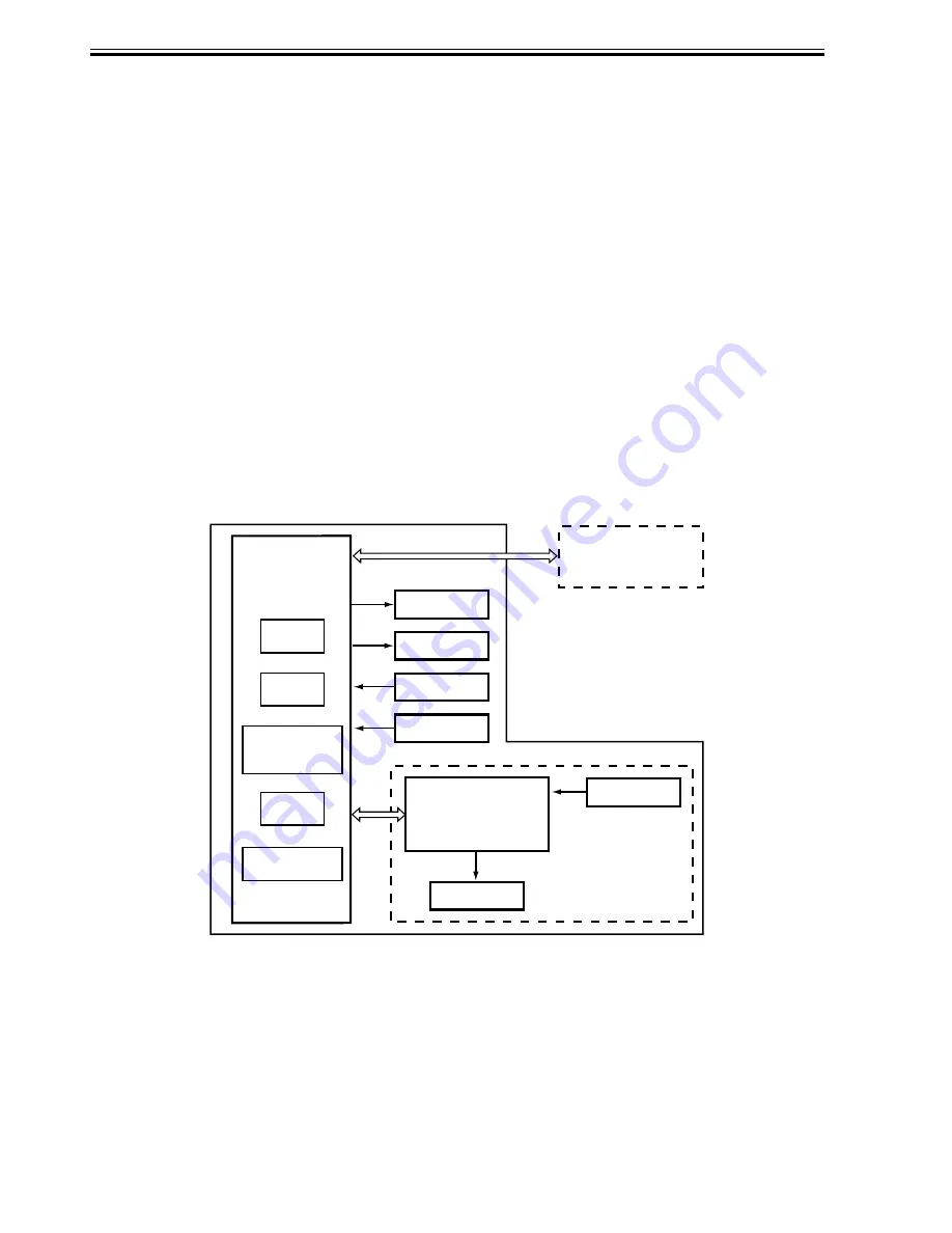
The sequence of finisher operations is controlled by the finisher controller PCB. The fin-
isher controller PCB is a 16-bit microprocessor (CPU), and is also used for combination with
the host machine (serial).
The finisher controller PCB drive motors and other loads in response to the various com-
mands from the host machine. It also communicates such data as on the states of various sen-
sors and switches to the host machine by way of the serial communication line.
The ICs mounted to the finisher controller PCB have the following functions:
Host machine DC
controller PCB
CPU
Punch controller
PCB
Finisher
controller
PCB
IC13
CPU
IC12
EEP-ROM
IC11
Communica-
tion IC
IC6
EP-ROM
IC1
Regulator IC
Motor
Clutch
Switch
Sensor
Motor
Sensor
Finisher unit
Puncher unit (option)
•
IC13 (CPU)
Controls sequence of operations.
•
IC12 (EEP-ROM)
Backs up adjustment settings.
•
IC6 (EP-ROM)
Stores sequence programs.
•
IC11 (communication IC)
Communicates with the host machine.
•
IC1 (regulator IC)
Generates 5 V.
F02-102-01
F02-102-01 shows the flow of signals between finisher and options controller:
Содержание DF-75
Страница 1: ...SERVICE MANUAL Published in Aug 01 5FG70760 DF 75...
Страница 12: ...CHAPTER 1 GENERAL DESCRIPTION...
Страница 24: ...CHAPTER 2 OUTLINE OF OPERATION...
Страница 89: ...CHAPTER 3 MECHANICAL SYSTEMS...
Страница 108: ...3 19 CHAPTER 3 MECHANICAL SYSTEMS 3 Detach the timing belt 3 and remove the two screws 4 F03 102 26 3 4 4...
Страница 132: ...CHAPTER 4 MAINTENANCE AND INSPECTION...
Страница 135: ...CHAPTER 5 TROUBLESHOOTING...
Страница 142: ...5 7 CHAPTER 5 TROUBLESHOOTING...
Страница 145: ...5 10 CHAPTER 5 TROUBLESHOOTING 2 1 2 Motor PCBs M7 M8 M5 M4 M3 M6 M1 M2 1 F05 201 02...
Страница 175: ...5 40 CHAPTER 5 TROUBLESHOOTING...
Страница 176: ...APPENDIX...
Страница 180: ...A 4...
Страница 184: ...A 8 APPENDIX...
Страница 198: ...A 22...


