3-39
CHAPTER 3 MECHANICAL SYSTEMS
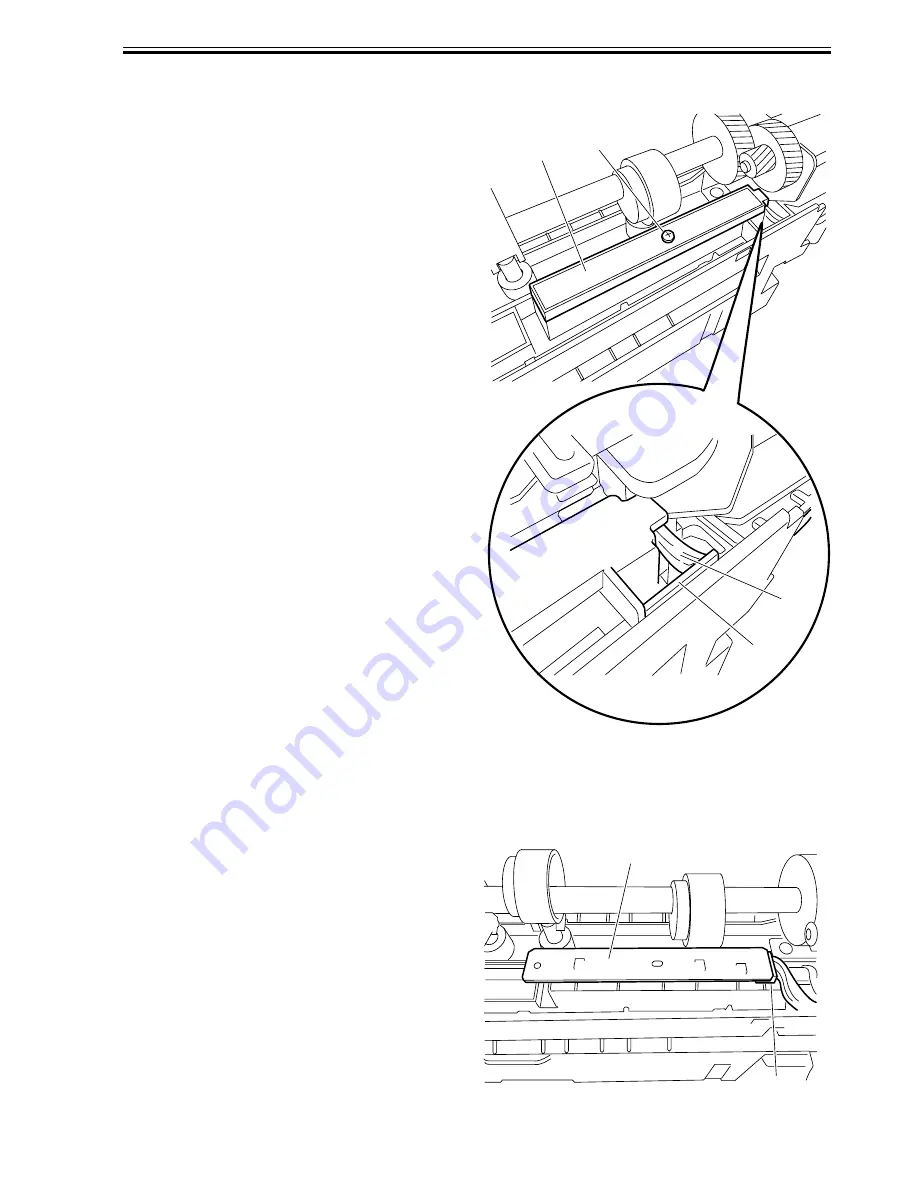
2.2.2 Removing the Photosensor PCB
1) Remove the punch motor. (See 2.1.1.)
2) Remove the screw [1].
3) Remove the harness [3] from the harness
guide [2] on the PCB, then detach the
PCB cover [4].
F03-202-02
4) Disconnect the connector [5] to remove
the photosensor PCB [6].
F03-202-03
[4]
[1]
[2]
[3]
[6]
[5]
Содержание DF-75
Страница 1: ...SERVICE MANUAL Published in Aug 01 5FG70760 DF 75...
Страница 12: ...CHAPTER 1 GENERAL DESCRIPTION...
Страница 24: ...CHAPTER 2 OUTLINE OF OPERATION...
Страница 89: ...CHAPTER 3 MECHANICAL SYSTEMS...
Страница 108: ...3 19 CHAPTER 3 MECHANICAL SYSTEMS 3 Detach the timing belt 3 and remove the two screws 4 F03 102 26 3 4 4...
Страница 132: ...CHAPTER 4 MAINTENANCE AND INSPECTION...
Страница 135: ...CHAPTER 5 TROUBLESHOOTING...
Страница 142: ...5 7 CHAPTER 5 TROUBLESHOOTING...
Страница 145: ...5 10 CHAPTER 5 TROUBLESHOOTING 2 1 2 Motor PCBs M7 M8 M5 M4 M3 M6 M1 M2 1 F05 201 02...
Страница 175: ...5 40 CHAPTER 5 TROUBLESHOOTING...
Страница 176: ...APPENDIX...
Страница 180: ...A 4...
Страница 184: ...A 8 APPENDIX...
Страница 198: ...A 22...


