5-5
CHAPTER 5 TROUBLESHOOTING
1.2.3 Registering the Number of Punch Hole
Perform the following to register the type of puncher unit (number of holes) used to the IC
on the punch controller PCB for identification by the finisher. Be sure to register the type
whenever you have replaced the punch controller PCB.
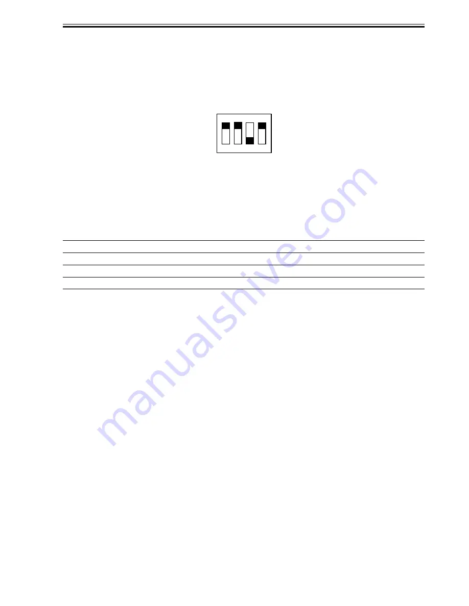
1) Set bits 1 through 4 on the DIPSW1001 on the punch controller PCB as follows:
F05-102-02
2) Press SW1002 on the punch controller PCB to select the appropriate number of punch
holes.
•
Each press on SW1002 moves the selection through the following (repeatedly from top to
bottom).
Number of punch holes
2 holes (Puncher Unit-J1)
2/3 holes (Puncher Unit-K1)
4 holes (Puncher Unit-G1)
4 holes (Puncher Unit-H1)
LED1002
OFF
ON
ON
OFF
LED1003
OFF
OFF
OFF
ON
LED1001
ON
ON
OFF
OFF
ON
1
2
3
4
T05-102-01
3) Press SW1003 on the punch controller PCB twice. The presses will store the selected
number of punch holes on the punch controller PCB.
•
A single press on SW1003 will cause the LED indication to flash; another press on
SW1003 will cause the indication to remain ON to indicate the end of registration.
4) Shift all bits of DIPSW1001 to OFF.
Содержание DF-75
Страница 1: ...SERVICE MANUAL Published in Aug 01 5FG70760 DF 75...
Страница 12: ...CHAPTER 1 GENERAL DESCRIPTION...
Страница 24: ...CHAPTER 2 OUTLINE OF OPERATION...
Страница 89: ...CHAPTER 3 MECHANICAL SYSTEMS...
Страница 108: ...3 19 CHAPTER 3 MECHANICAL SYSTEMS 3 Detach the timing belt 3 and remove the two screws 4 F03 102 26 3 4 4...
Страница 132: ...CHAPTER 4 MAINTENANCE AND INSPECTION...
Страница 135: ...CHAPTER 5 TROUBLESHOOTING...
Страница 142: ...5 7 CHAPTER 5 TROUBLESHOOTING...
Страница 145: ...5 10 CHAPTER 5 TROUBLESHOOTING 2 1 2 Motor PCBs M7 M8 M5 M4 M3 M6 M1 M2 1 F05 201 02...
Страница 175: ...5 40 CHAPTER 5 TROUBLESHOOTING...
Страница 176: ...APPENDIX...
Страница 180: ...A 4...
Страница 184: ...A 8 APPENDIX...
Страница 198: ...A 22...


