3-18
Disassembly/Assembly
Top Enclosure
Replacing the Engine Board
1. Place the Engine Board in position on the top enclosure.
Note
: Be sure the blue xD Daughtercard bezel is seated in the rear panel cutout properly.
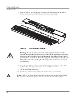
2. Align the center screw hole on the front panel edge with the thread marks in the extrusion
and install the three screws that secure the front panel edge. See Figure 3-14.
3. Install the two screws that secure the USB/xD Daughtercard to the rear panel.
4. Connect the
fl
at ribbon cable from the LCD to J15 on the Engine Board.
5. Connect the stranded wire cables from the Connector Board to J5, J21, and J33 on the
Engine Board.
6. Connect the shielded wire cable from the Connector Board to J18 on the Engine Board.
Removing the USB/xD Daughtercard
The USB/xD Daughtercard is mounted on the Engine Board and is held in place with a 28-pin
connector.
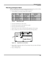
1. Follow the procedure described on page 3-17 to remove the Engine Board.
2. Lift the USB/xD Daughtercard straight up to disconnect it from J12 on the Engine Board.
Replacing the USB/xD Daughtercard
1. Position the USB/xD Daughtercard over the 28-pin connector at J12 on the Engine Board.
2. Verify that the Engine Board pins are lined up properly with the 28-pin connector on the
USB/xD Daughtercard. Press the USB/xD Daughtercard down to insert the pins into the
28-pin connector.
3. Follow the procedure described on page 3-18 to install the Engine Board.
Содержание PC3x
Страница 14: ...1 6 Introduction PC3x Front Panel...
Страница 24: ...2 10 Diagnostics Description of Tests...
Страница 50: ...3 26 Disassembly Assembly PC3x Keyboard Assembly...
Страница 72: ...4 22 Troubleshooting Maintenance Converting the Voltage...

