Disassembly/Assembly
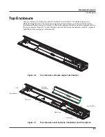
Top Enclosure
3-15
Note
: If the service you are performing only requires that you have access to the Front Panel
Board for component testing or component replacement, it is not necessary to separate the LCD
Board from Front Panel Board.
5. If you are replacing the Front Panel Board with another board, follow the procedure
described on page 3-13 to remove the LCD Board.
Note
: If you are replacing the Front Panel Board with another board, be sure to remove the four
screws that secure the LCD bezel to the board and install it on the new board.
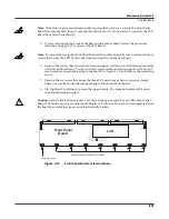
6. Seven of the screws that secure the enclosure support wall also secure the front panel edge
of the Front Panel Board. You have already removed the enclosure support wall, but one
screw remains securing this edge of the board. See Figure 3-13, and remove the remaining
screw.
7. Remove the six screws that secure the three PC board clamps (two screws per clamp).
These screws also secure the rear panel edge of the Front Panel Board.
8. Lift the Front Panel Board up from the top enclosure. The spinknob and switch button
caps should remain in place.
Caution
: Each switch button cap uses a set of small pegs to mount the cap to the Front Panel
Board. The button caps are mounted individually or in clusters. If a cap becomes separated from
the board, be careful that a peg is not inadvertently broken.
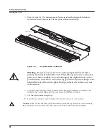
Figure 3-13
Front Panel Board, screw locations
J202
J201
FP Bridge
J203-2 RETURN BLACK
J203-1 HOT BLUE
1
1
LCD
Front Panel
Board
Enclosure Support Wall screw locations
remaining screw
Содержание PC3x
Страница 14: ...1 6 Introduction PC3x Front Panel...
Страница 24: ...2 10 Diagnostics Description of Tests...
Страница 50: ...3 26 Disassembly Assembly PC3x Keyboard Assembly...
Страница 72: ...4 22 Troubleshooting Maintenance Converting the Voltage...


