Diagnostics
Description of Tests
2-5
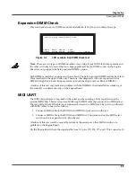
Expansion DIMM Check
This test checks to see if a DIMM module is installed in J10 or J11 and con
fi
rms the type.
Figure 2-4
LCD example, Exp DIMM check test
Note
: There are two types of DIMM modules—one with all four NOR Flash chips present and
the other with only two out of the four chips populated. The J10 DIMM socket on the Engine
Board can only support the half-populated DIMM version.
Each DIMM module has an upper and lower bank. The half-populated DIMM module has Flash
chips installed in the upper bank only. Therefore, this diagnostic will only report results for
DIMM 0, High Bank; but will report results for both the High and Low Bank of DIMM 1.
A failure of this test may indicate a problem with the DIMM(s), their installation, soldering of
the socket(s), or related circuitry on the Engine Board.
MIDI UART
The MIDI test performs a loop-back of the serial port by sending a 23-byte pattern over the
external MIDI link. This test requires a MIDI loop (a MIDI cable that connects two MIDI jacks).
The test will fail if a MIDI cable is not connected between two MIDI jacks. Be sure to run this test
with MIDI cables connected as follows:
1. Connect a MIDI cable to the MIDI In and MIDI Out jacks and run the test.
2. Connect a MIDI cable to the MIDI In and MIDI Out/Thru jacks and set the MIDI select
switch on the rear panel to Out. Run the test.
A failure of this test could be caused by failure of the serial port, other MIDI circuitry, or a
problem on the Engine Board.
On the Engine Board check the signal paths from U1, pins 172, 174, 177, and 179 to connector J5.
Running Exp DIMM check test
CHECK READ WRITE PLAY
DIMMS DIMMS DIMMS DIMMS EXIT
Содержание PC3x
Страница 14: ...1 6 Introduction PC3x Front Panel...
Страница 24: ...2 10 Diagnostics Description of Tests...
Страница 50: ...3 26 Disassembly Assembly PC3x Keyboard Assembly...
Страница 72: ...4 22 Troubleshooting Maintenance Converting the Voltage...


