DATAFLEX
®
42/1000
Torque Measuring Shaft
Operating/Assembly instructions
KTR-N
Sheet:
Edition:
49016 EN
9 of 21
2
Please observe protection
note ISO 16016.
Drawn:
2017-01-02 Shg/Koe
Replaced for:
KTR-N dated 2015-04-13
Verified:
2017-01-02 Shg
Replaced by:
Table 4: Displacement figures
DATAFLEX
®
size
RADEX
®
-N size
Max. axial displace-
ment
K
a
[mm]
Max. radial displacement
K
r
[mm]
Max. angular displace-
ment
K
w
[degree]
42/1000
80
2.6
4.1
1.0
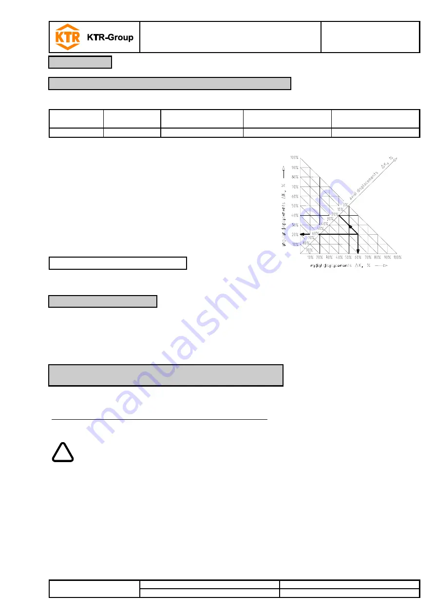
Examples of the displacement combina-
tions specified in illustration 6:
Example:
K
r
= 60%
K
w
= 20%
K
a
= 20%
Illustration 6:
Combinations of
displacement
K
total
=
K
a
+
K
r
+
K
w
100%
We recommend to inspect bores, shaft, keyway and feather key for dimensional accuracy
before assembly.
The power transmission is frictionally engaged. Fit pair of shaft-clamping ring hub is specified with H7/h6.
The following process should be observed with the assembly:
Please clean and degrease the contact surfaces of the hub bores and the shafts before assembly.
!
Oils and greases containing molybdenum disulfide or other high-pressure additives as well
as internal lubricants must not be used.
Lightly unscrew the clamping scews, shift the clamping ring hub onto the shaft of the measuring shaft and
align to dimension L
6.
Tighten the clamping screws evenly crosswise. Increase the tightening torque stepwise.
Repeat this process until the tightening torque specified in table 5 has been achieved with all clamping screws.
4
Assembly
4.3 Displacements - alignment of the torque measuring shaft
4.4 Assembly of the hubs
4.5 Assembly of the RADEX
®
-N clamping ring hubs on the
DATAFLEX
®
torque measuring shaft


