background image

GENERAL TIPS AND HINTS ON PUTTING INTO OPERATION

18

6.7

Preparations for riding at high temperatures and riding slowly

600872-10

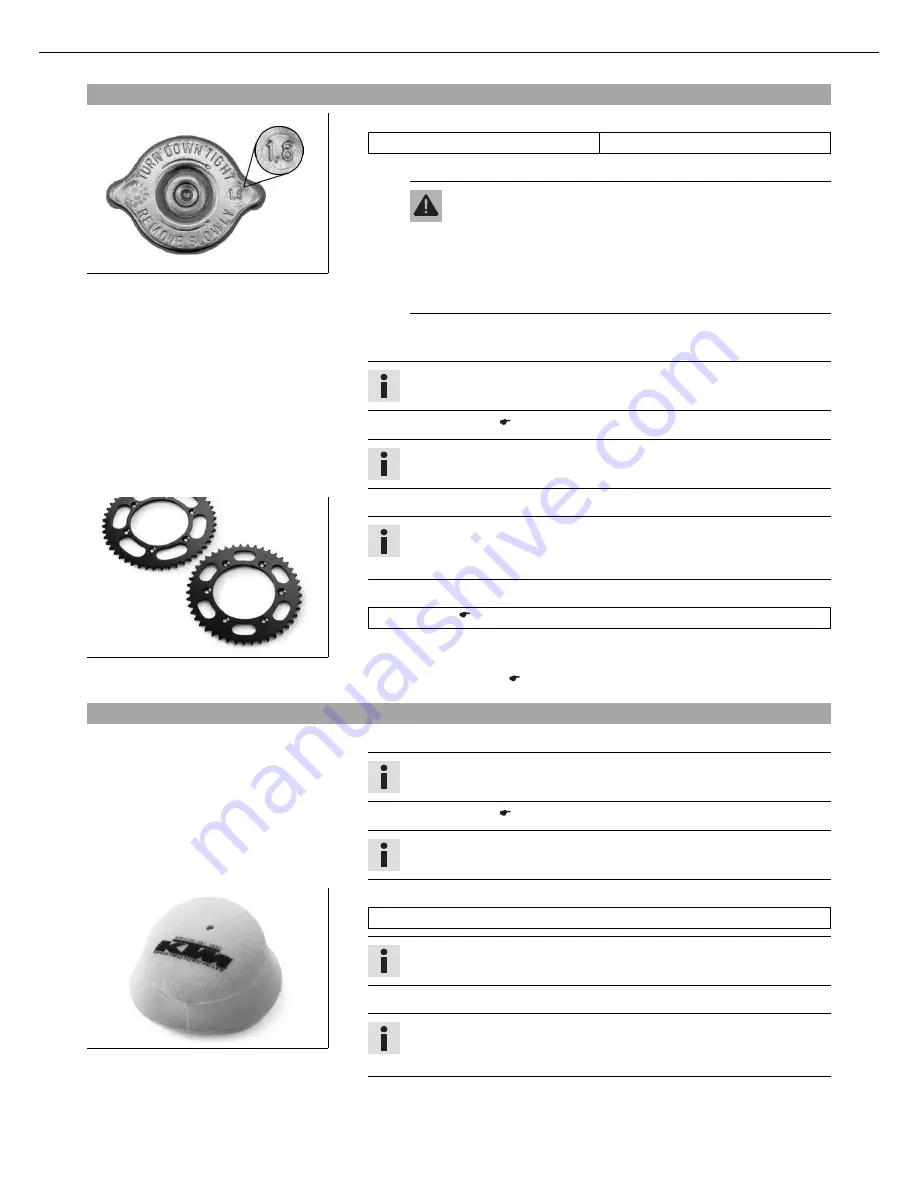
Check the radiator cap.

Value on radiator cap

1.8 bar (26 psi)

» If the value displayed does not meet specifications:

Warning

Danger of scalding

During motorcycle operation, the coolant gets

very hot and is under pressure.

Do not remove the radiator cap, radiator hoses or other cooling
system components when the engine is hot. Allow the engine
and cooling system to cool down. In case of scalding, rinse
immediately with lukewarm water.

Change the radiator cap.

Seal the air filter box.

x

Tip

Seal the air filter box at the edges to prevent dirt from entering.

Clean the air filter.

x

(

p. 63)

Info

Check the air filter approx. every 30 minutes.

600868-01

Adjust the secondary ratio to the nature of the terrain.

Info

The engine oil heats up quickly if the clutch needs to be activated
frequently because the secondary ratio is too long.

Clean the chain.

Chain cleaner (

p. 96)

Clean the radiator fins.

Carefully align bent radiator fins.

Check the coolant level. (

p. 59)

6.8

Preparations for riding at low temperatures and in snow

Seal the air filter box.

x

Tip

Seal the air filter box at the edges to prevent dirt from entering.

Clean the air filter.

x

(

p. 63)

Info

Check the air filter approx. every 30 minutes.

600870-01

Mount the rain cover for the air filter.

Rain cover for air filter (59006021000)

Info

Follow the

KTM PowerParts

mounting instructions.

Adjust the carburetor jetting and setting.

Info

The recommended carburetor tuning is available from your authorized KTM
workshop.

Содержание 125 SX 2010

Страница 1: ...MANUALE O USO MANUEL D UTILISATION MANUAL DE INSTRUCCIONES REPARATURANLEITUNG REPAIR MANUAL MANUALE DI REPARAZIONE MANUEL DE REPARATION MANUAL DE REPARACION FEDERBEIN SHOCK ABSORBER AMMORTIZZATORE AMMORTISSEUR AMORTIGUADOR GABEL FORK FORCELLA FOURCHE HORQUILLA ...

Страница 2: ...OWNERSMANUAL2010 250 SX 250 300 XC XC W EXC EXC SixDays ...

Страница 3: ...OWNER S MANUAL 2010 125 SX 150 SX 250 SX Art no 3211480en ...

Страница 4: ... the spring preload of the shock absorber x 29 Adjusting the riding sag x 30 Removing the shock absorber x 30 Installing the shock absorber x 31 Checking the basic setting of the fork 31 Adjusting the compression damping of the fork 31 Adjusting the rebound damping of the fork 32 Bleeding the fork legs 32 Cleaning the dust boots of the fork legs 32 Loosening the fork protection 33 Positioning the ...

Страница 5: ...Checking the basic position of the shift lever 66 Adjusting the basic position of the shift lever x 66 Carburetor 66 Carburetor adjusting the idle speed x 67 Emptying the carburetor float chamber x 68 Checking the gear oil level 68 Changing the gear oil x 69 Draining the gear oil x 69 Refilling with gear oil x 70 Adding gear oil x 70 TROUBLESHOOTING 72 CLEANING 74 Cleaning the motorcycle 74 STORAG...

Страница 6: ...standing In the interest of your own safety have these jobs done in an authorized KTM workshop There your motorcycle will be serviced optimally by specially trained experts using the specialist tools required Identifies a page reference more information is provided on the specified page Formats used The typographical and other formats used are explained below Specific name Identifies a specific na...

Страница 7: ...wner s manual Spare parts accessories For your own safety only use spare parts and accessory products that have been approved and or recommended by KTM and have them installed by an authorized KTM workshop KTM accepts no liability for other products and any resulting damage or loss Certain spare parts and accessories are specified in parentheses in the descriptions Your KTM dealer will be glad to ...

Страница 8: ...mmediately and invariably lead to fatal or serious permanent injury if the appropriate measures are not taken Warning Identifies a danger that is likely to lead to fatal or serious injury if the appropriate measures are not taken Note Identifies a danger that will lead to considerable machine and material damage if the appropriate measures are not taken Warning Identifies a danger that will lead t...

Страница 9: ...OF VEHICLE 7 3 1 View of the vehicle from the left front example B00010 10 1 Hand brake lever 2 Short circuit button 3 Clutch lever 4 Air filter box lid 5 Fuel tap 6 Choke button 7 Shift lever 8 Chain guide ...

Страница 10: ...ht rear example B00014 10 1 Shock absorber rebound adjustment 2 Level viewer for brake fluid rear 3 Fork rebound adjustment 4 Foot brake lever 5 Kickstarter 6 Shock absorber compression adjustment 7 Throttle grip 8 Fork compression adjustment 9 Filler cap ...

Страница 11: ...f the steering head 4 3 Engine number B00016 10 The engine number is stamped on the left side of the engine under the engine sprocket 4 4 Fork part number 500082 10 The fork part number is stamped on the inner side of the fork stub 4 5 Shock absorber part number 500083 10 The shock absorber part number is stamped on the top of the shock absorber above the adjusting ring on the engine side ...

Страница 12: ...ted on the right side of the handlebar The hand brake lever is used to activate the front brake 5 3 Short circuit button B00002 10 Short circuit button is fitted on the left side of the handlebar Possible states Short circuit button in basic position In this position the ignition circuit is closed and the engine can be started Short circuit button pressed In this position the ignition circuit is i...

Страница 13: ...clockwise and lift it free 5 7 Closing the filler cap 400199 11 Replace the filler cap and turn clockwise until the release button locks in place Info Run the fuel tank breather hose without kinks 5 8 Choke B00004 10 The choke is fitted on the left side of the carburetor Activating the choke function frees an opening through which the engine can draw extra fuel This gives a richer fuel air mixture...

Страница 14: ...st and second gears B00005 11 250 SX The gear positions can be seen in the photograph The neutral or idle position is between the first and second gears 5 10 Kickstarter B00006 10 The kickstarter is fitted on the right side of the engine The top part can be swiveled 5 11 Foot brake lever B00007 10 Foot brake lever is located in front of the right footrest The foot brake lever is used to activate t...

Страница 15: ...te Danger of damage The parked vehicle can roll away or fall over Always place the vehicle on a firm and even surface To park the motorcycle insert plug in stand into the left side of the wheel spindle Info Remove the plug in stand before riding ...

Страница 16: ...ot off the foot brake lever if you do not want to brake Warning Danger of accidents Unstable riding behavior Do not exceed the maximum permissible weight and axle loads Warning Risk of misappropriation Usage by unauthorized persons Never leave the vehicle while the engine is running Secure the vehicle against use by unauthorized persons Info When using your motorcycle remember that others may feel...

Страница 17: ...t may be necessary to service or replace worn parts before the limit specified in the service schedule is reached Difficult operating conditions are Riding on dry sand p 15 Riding on wet sand p 16 Riding on wet and muddy surfaces p 17 Riding at high temperatures and riding slowly p 18 Riding at low temperatures and in snow p 18 6 4 Preparations for riding on dry sand 600872 10 Check the radiator c...

Страница 18: ...icate the chain Clean the radiator fins Carefully align bent radiator fins 6 5 Preparations for riding on wet sand 600872 10 Check the radiator cap Value on radiator cap 1 8 bar 26 psi If the value displayed does not meet specifications Warning Danger of scalding During motorcycle operation the coolant gets very hot and is under pressure Do not remove the radiator cap radiator hoses or other cooli...

Страница 19: ...ator fins Carefully align bent radiator fins 6 6 Preparations for riding on wet and muddy surfaces Seal the air filter box x Tip Seal the air filter box at the edges to prevent dirt from entering Clean the air filter x p 63 Info Check the air filter approx every 30 minutes 600870 01 Mount the rain cover for the air filter Rain cover for air filter 59006021000 Info Follow the KTM PowerParts mountin...

Страница 20: ...e air filter x p 63 Info Check the air filter approx every 30 minutes 600868 01 Adjust the secondary ratio to the nature of the terrain Info The engine oil heats up quickly if the clutch needs to be activated frequently because the secondary ratio is too long Clean the chain Chain cleaner p 96 Clean the radiator fins Carefully align bent radiator fins Check the coolant level p 59 6 8 Preparations ...

Страница 21: ...h When running the engine always make sure there is sufficient ventilation and do not start or run the engine in an enclosed space without an effective exhaust extraction system Note Engine failure High engine speeds in cold engines have a negative effect on the service life of the engine Always warm up the engine at low engine speeds Info If the motorcycle is unwilling to start the cause can be o...

Страница 22: ... throttle opening increases fuel consumption To shift down brake and close the throttle at the same time Pull the clutch lever and shift into a lower gear release the clutch lever slowly and open the throttle or shift again Switch off the engine if you expect to be standing for a long time Guideline 2 min Avoid frequent and longer slipping of the clutch This heats the engine oil the engine and the...

Страница 23: ...and the motorcycle could fall over Brake the motorcycle Shift gear to neutral Press and hold the short circuit button while the engine is idling until the engine stops Turn handle of the fuel tap to the OFF position Figure B00003 10 p 11 Insert the plug in stand on the left side of the wheel spindle Park the motorcycle on firm ground 7 7 Refueling Danger Fire hazard Fuel is highly flammable Never ...

Страница 24: ...measurement Guideline Measurement of 35 mm 1 38 in Total fuel tank capacity approx 8 l 2 1 US gal Super unleaded gasoline mixed with 2 stroke engine oil 1 40 p 95 125 SX 150 SX Super unleaded gasoline mixed with 2 stroke engine oil 1 60 p 95 250 SX Close the filler cap p 11 ...

Страница 25: ... brake discs p 42 Check the front brake fluid level p 43 Check the rear brake fluid level p 47 Check the brake lines for damage and leakage Check the free travel of the hand brake lever p 43 Check the free play of the foot brake lever p 46 Check the brake system function Check the screws and guide bolts of the brake system for tightness Chassis Check the shock absorber and fork for leakage and fun...

Страница 26: ...at electric contacts with contact spray S10A Every 10 service hours corresponds to about 70 liters of fuel 18 5 US gal S20N Once after 20 service hours corresponds to about 140 liters of fuel 37 US gal S20A Every 20 service hours corresponds to about 140 liters of fuel 37 US gal S30A Every 30 service hours corresponds to about 210 liters of fuel 55 5 US gal S40A Every 40 service hours corresponds ...

Страница 27: ...oolant level p 59 Empty the carburetor float chamber x p 68 Check all controls for smooth operation Check braking Check all screws nuts and hose clamps regularly for tightness NB1A Depending on conditions of use according to requirements ...

Страница 28: ...djusted for a standard rider weight with full protective clothing Guideline Standard rider weight 75 85 kg 165 187 lb If your weight is above or below the standard range you need to adjust the basic setting of the suspension components accord ingly Small weight differences can be compensated by adjusting the spring preload but in the case of large weight differences the springs must be replaced 9 ...

Страница 29: ...accidents Disassembly of pressurized parts can lead to injury The shock absorber is filled with high density nitrogen Adhere to the description provided Your authorized KTM workshop will be glad to help Info The low speed setting can be seen during the slow to normal compression of the shock absorber 400209 10 Turn adjusting screw clockwise with a screwdriver up to the last perceptible click Info ...

Страница 30: ...terclockwise by the number of clicks corresponding to the shock absorber type Guideline 125 SX 150 SX Rebound damping Comfort 24 clicks Standard 22 clicks Sport 22 clicks 250 SX Rebound damping Comfort 24 clicks Standard 22 clicks Sport 22 clicks Info Turn clockwise to increase damping turn counterclockwise to reduce damp ing 9 8 Measuring the sag of the unloaded rear wheel Jack up the motorcycle ...

Страница 31: ...ve clothing sits on the saddle in the normal sitting position feet on footrests and bounces up and down a few times until the rear suspension levels out The other person now measures the distance between the rear axle and a fixed point Make a note of the value as measurement Info The riding sag is the difference between measurements and Check the riding sag Guideline 125 SX 150 SX Riding sag 107 m...

Страница 32: ...oose and mount a suitable spring Guideline 125 SX 150 SX Spring rate Weight of rider 65 75 kg 143 165 lb 60 N mm 343 lb in Weight of rider 75 85 kg 165 187 lb 63 N mm 360 lb in Weight of rider 85 95 kg 187 209 lb 66 N mm 377 lb in 250 SX Spring rate Weight of rider 65 75 kg 143 165 lb 66 N mm 377 lb in Weight of rider 75 85 kg 165 187 lb 69 N mm 394 lb in Weight of rider 85 95 kg 187 209 lb 72 N m...

Страница 33: ...or various reasons no exact riding sag can be determined for the forks 400189 01 As with the shock absorber smaller weight differences can be compensated by the spring preload However if your fork often bottoms out hard end stop on compression you must fit harder springs to avoid damage to the fork and frame 9 16 Adjusting the compression damping of the fork Info The hydraulic compression damping ...

Страница 34: ...by the number of clicks corresponding to the fork type Guideline 125 SX 150 SX Rebound damping Comfort 14 clicks Standard 12 clicks Sport 10 clicks 250 SX Rebound damping Comfort 14 clicks Standard 12 clicks Sport 10 clicks Info Turn clockwise to increase damping turn counterclockwise to reduce damp ing Mount protection covers 9 18 Bleeding the fork legs Jack up the motorcycle p 26 B00018 10 Remov...

Страница 35: ...rews and take off the clamp Remove screws on the left fork leg Push the fork protection downwards Remove the screws on the right fork leg Push the fork protection downwards 9 21 Positioning the fork protection B00013 10 Position the fork protection on the left fork leg Mount and tighten screws Guideline Remaining screws chassis M6 10 Nm 7 4 lbf ft Position the brake line Position the clamp and mou...

Страница 36: ...torcycle from the work stand p 26 9 23 Adjusting the play of the steering head bearing x Jack up the motorcycle p 26 B00019 10 Loosen screws Remove screw Loosen and retighten screw Guideline Screw top steering head M20x1 5 10 Nm 7 4 lbf ft Using a plastic hammer tap lightly on the upper triple clamp to avoid strains Tighten screws Guideline Screw top triple clamp M8 17 Nm 12 5 lbf ft Mount and tig...

Страница 37: ...brake caliper M8 25 Nm 18 4 lbf ft Loctite 243 Position the brake line Put the clamp on and mount and tighten screws Install the front wheel x p 51 9 26 Removing the fork protector x Remove the fork legs x p 34 500105 10 Remove screws on the left fork leg Lift off the fork protector Remove the screws on the right fork leg Lift off the fork protector 9 27 Installing the fork protector x 500105 10 P...

Страница 38: ...ing stem Take out the upper steering head bearing 9 29 Installing the lower triple clamp x 0 0 2 2 0 0 1 1 0 0 3 3 B00024 10 Clean the bearing and sealing elements check for damage and grease Long life grease p 96 Insert the lower triple clamp with the steering stem Mount the upper steering head bearing Info Check whether the top steering head seal is correctly positioned Push up protective ring a...

Страница 39: ...ower triple clamp x p 36 Install the lower triple clamp x p 36 9 31 Removing the front fender 500092 10 Remove screws Remove the front fender Make sure the spacers remain in place 9 32 Installing the front fender 500092 10 Ensure that the spacers are mounted in the fender Position the front fender Mount and tighten screws Guideline Remaining screws chassis M6 10 Nm 7 4 lbf ft Info Make sure the ho...

Страница 40: ...ons In this way the handlebar can be mounted in the position that is most comfortable for the rider 9 36 Adjusting the handlebar position x 0 0 2 2 0 0 1 1 B00025 10 Remove the four screws Remove the handlebar clamp Remove the handlebar and lay it to one side Info Protect the motorcycle and its attachments against damage by covering them Do not bend the cables and lines Remove the two screws Remov...

Страница 41: ...e outer casing of the throttle cable Guideline Play in throttle cable 3 5 mm 0 12 0 2 in Tighten the nut Push on bellows Check the throttle grip for smooth operation 9 39 Checking the chain for dirt 400678 01 Check the chain for heavy soiling If the chain is very dirty Clean the chain p 39 9 40 Cleaning the chain Warning Danger of accidents Oil or grease on the tires reduces their grip Remove oil ...

Страница 42: ...eces sary Jack up the motorcycle p 26 400213 10 Push the chain at the end of the chain sliding component upwards to measure chain tension Info The upper chain section must be taut Chain wear is not always even so you should repeat this measurement at different chain positions Chain tension 8 10 mm 0 31 0 39 in If the chain tension does not meet specifications Adjust the chain tension p 41 Remove t...

Страница 43: ...rcycle from the work stand p 26 9 44 Adjusting the chain tension Warning Danger of accidents Danger caused by incorrect chain tension If the chain tension is too high the components of the secondary power train chain engine sprocket rear sprocket bear ings in transmission and rear wheel are under additional load Apart from premature wear in extreme cases the chain can rupture or the countershaft o...

Страница 44: ...9 45 Adjusting the chain guide x 400224 10 Unscrew screw Remove screw Swing the chain guide down Condition Number of teeth 44 teeth Insert collar bushing in hole Position the chain guide Mount and tighten screw Tighten screw Guideline Remaining screws chassis M6 10 Nm 7 4 lbf ft Condition Number of teeth 45 teeth Insert collar bushing in hole Position the chain guide Mount and tighten screw Tighte...

Страница 45: ...ake lever to your hand size by turning adjust ing screw Info Turn the adjusting screw clockwise to increase the distance between the hand brake lever and the handlebar Turn the adjusting screw counterclockwise to decrease the distance between the hand brake lever and the handlebar The range of adjustment is limited Turn the adjusting screw by hand only and do not apply any force Do not make any ad...

Страница 46: ...onmental hazard Hazardous substances cause environmental damage Oil grease filters fuel cleaners brake fluid etc should be disposed of as stipulated in applicable regulations Info Never user DOT 5 brake fluid This is based on silicone oil and is colored purple Oil seals and brake lines are not designed for DOT 5 brake fluid Avoid contact between brake fluid and painted parts Brake fluid attacks pa...

Страница 47: ...e brake discs Always keep the brake discs free of oil and grease and clean them with brake cleaner when necessary Warning Danger of accidents Reduced braking efficiency due to use of non approved brake linings Brake linings available from accessory suppliers are often not tested and approved for use on KTM vehicles The construc tion and friction factor of the brake linings and therefore the brake ...

Страница 48: ...ean brake fluid from a sealed container 600706 10 Remove the front brake linings x p 45 Move the brake fluid reservoir mounted on the handlebar to a horizontal position Remove screws Remove cover with membrane Press the brake piston back to its basic position and make sure that no brake fluid overflows from the brake fluid reservoir Install the front brake linings x p 45 Add brake fluid to level G...

Страница 49: ... basic position of the foot brake lever Guideline Free play of foot brake lever 3 5 mm 0 12 0 2 in Hold screw and tighten nut Guideline Remaining screws chassis M8 25 Nm 18 4 lbf ft Hold push rod and tighten nut Guideline Remaining nuts chassis M6 15 Nm 11 1 lbf ft Attach spring 9 57 Checking the rear brake fluid level Warning Danger of accidents Failure of the brake system If the brake fluid leve...

Страница 50: ...filters fuel cleaners brake fluid etc should be disposed of as stipulated in applicable regulations Info Never user DOT 5 brake fluid This is based on silicone oil and is colored purple Oil seals and brake lines are not designed for DOT 5 brake fluid Avoid contact between brake fluid and painted parts Brake fluid attacks paint Use only clean brake fluid from a sealed container 400233 10 Stand the ...

Страница 51: ...king efficiency due to use of non approved brake linings Brake linings available from accessory suppliers are often not tested and approved for use on KTM vehicles The construc tion and friction factor of the brake linings and therefore the brake power can differ considerably from the original KTM brake linings If brake linings are used that differ from the originals there is no guarantee that the...

Страница 52: ...is based on silicone oil and is colored purple Oil seals and brake lines are not designed for DOT 5 brake fluid Avoid contact between brake fluid and painted parts Brake fluid attacks paint Use only clean brake fluid from a sealed container 400233 10 Remove the rear brake linings x p 49 Stand the vehicle upright Remove screw cap with membrane and the O ring Press the brake piston back to its basic...

Страница 53: ...ree of oil and grease and clean them with brake cleaner when necessary 500086 11 Clean and grease shaft seal rings and bearing surface of the spacers Long life grease p 96 Insert the spacers 500084 11 Lift the front wheel into the fork position it and insert the wheel spindle Mount and tighten screw Guideline Screw front wheel spindle M24x1 5 45 Nm 33 2 lbf ft Operate the hand brake lever several ...

Страница 54: ...et Holding the rear wheel withdraw the wheel spindle Take the rear wheel out of the swingarm Info Do not operate the foot brake when the rear wheel is removed Always lay the wheel down in such a way that the brake disc is not dam aged 400260 11 Remove spacers 9 66 Installing the rear wheel x Warning Danger of accidents Reduced braking efficiency due to oil or grease on the brake discs Always keep ...

Страница 55: ... an important impact on the handling characteristics of the motorcycle The front and rear wheels must be mounted with tires with similar profiles Worn tires have a negative effect on handling characteristics especially on wet surfaces 400602 10 Check the front and rear tires for cuts run in objects and other damage If the tires exhibit cuts run in objects or other damage Change the tire Check the ...

Страница 56: ...spokes are too tight they can break due to local overload Check the spoke tension regularly especially on a new motorcycle 400694 01 Briefly strike each spoke with the tip of a screwdriver Info The tone frequency depends on the length of the spoke and the spoke diam eter If you hear different tone frequencies from different spokes of equal length and diameter this is an indication of different spo...

Страница 57: ...stic can be influenced by different spring strengths of the auxil iary spring 9 73 Engine characteristic adjusting the auxiliary spring x 250 SX Warning Danger of burns Some vehicle components get very hot when the vehicle is in use Do not touch hot components such as exhaust system radiator engine shock absorber and brakes Allow these compo nents to cool down before starting work on them Tilt the...

Страница 58: ...s or burning cigarettes and always switch off the engine first Be careful that no fuel is spilt especially on hot vehicle components Clean up spilt fuel immediately Fuel in the fuel tank expands when warm and can escape if the tank is overfilled See the notes on refueling Warning Danger of poisoning Fuel is poisonous and a health hazard Avoid contact between fuel and skin eyes and clothing Do not ...

Страница 59: ...n warm and can escape if the tank is overfilled See the notes on refueling Warning Danger of poisoning Fuel is poisonous and a health hazard Avoid contact of the fuel with skin eyes and clothing Do not inhale fuel vapors If fuel gets into your eyes rinse imme diately with water and contact a doctor Wash affected skin areas immediately with soap and water If fuel is swallowed contact a doctor immed...

Страница 60: ...ling effect Dirty cooling fins also reduce the cooling effect 9 79 Checking the antifreeze and coolant level Warning Danger of scalding During motorcycle operation the coolant gets very hot and is under pressure Do not remove the radiator cap radiator hoses or other cooling system components when the engine is hot Allow the engine and cooling system to cool down In case of scalding rinse immediate...

Страница 61: ...ght on a horizontal surface Remove the radiator cap Check the coolant level in the radiator Coolant level above the radiator fins 10 mm 0 39 in If the level of the coolant does not meet specifications Correct the coolant level Alternative 1 Coolant p 94 Alternative 2 Coolant mixed ready to use p 94 Mount the radiator cap 9 81 Draining the coolant x Warning Danger of scalding During motorcycle oper...

Страница 62: ...ous and a health hazard Avoid contact between coolant and skin eyes and clothing If fuel gets into your eyes rinse immediately with water and contact a doctor Wash affected skin areas immediately with soap and water If coolant is swallowed contact a doctor immediately Change clothes that have come into contact with coolants Keep coolant out of the reach of children B00071 10 125 SX 150 SX Make sur...

Страница 63: ...ith rubber sleeve Mount and tighten screws Guideline Remaining screws chassis M6 10 Nm 7 4 lbf ft 9 85 Glass fiber yarn filling of main silencer B00063 10 The main silencer is filled with glass fiber yarn Over a period the fibers of the insulating material vanish into the air and the silencer burns out Not only is the noise level higher the performance characteristic changes 9 86 Changing the glas...

Страница 64: ...hat are to be reinstalled 9 88 Installing the glass fiber yarn filling of the main silencer x 0 0 3 3 0 0 4 4 0 0 2 2 0 0 1 1 B00074 10 Slide the glass fiber yarn filling over the inner tube Slide the outer tube over the glass fiber yarn filling Info Ensure that the O rings are seated properly Insert locking cap into the outer tube Mount and tighten nut Install the main silencer p 61 9 89 Removing...

Страница 65: ...nstalling the air filter x 301262 10 Mount the clean air filter onto the air filter support Grease the air filter in area Long life grease p 96 B00039 10 Put in both parts together position them and fix them with air filter holder Info If the air filter is not correctly mounted dust and dirt can penetrate into the engine and can cause damage Install the air filter box lid p 62 9 93 Cleaning the ai...

Страница 66: ...ng screw counterclockwise to decrease the distance between the clutch lever and the handlebar Turn the adjusting screw clockwise to increase the distance between the clutch lever and the handlebar The range of adjustment is limited Turn the adjusting screw by hand only and do not apply any force Do not make any adjustments while riding 9 95 Checking the fluid level of the hydraulic clutch Info The...

Страница 67: ...d Bleed syringe 50329050000 Hydraulic fluid 15 p 94 On the slave cylinder remove bleeder screw and mount bleeding syringe 400247 10 Inject the liquid into the system until it escapes from hole of the master cylinder without bubbles To prevent overflow drain fluid occasionally from the master cylinder reservoir Remove the bleeding syringe Mount and tighten the bleeder screw Correct the fluid level ...

Страница 68: ... 66 9 98 Adjusting the basic position of the shift lever x B00065 10 Remove screw and remove shift lever B00066 10 Clean gear teeth of the shift lever and shift shaft Mount the shift lever on the shift shaft in the required position and engage the gearing Info When positioning the shift lever ensure that there is sufficient distance to the adjacent components Mount and tighten the screw Guideline ...

Страница 69: ...speed the jet needle must be raised If the behavior described above is exhibited while in idle or just above idle the idle system must be run leaner if there is stuttering and richer if there is knocking Full load range D Operation with the throttle slide fully opened full throttle This range is influenced by the main jet and jet needle If the insulator of a new spark plug is very light or white a...

Страница 70: ...k is overfilled See the notes on refueling Warning Danger of poisoning Fuel is poisonous and a health hazard Avoid contact between fuel and skin eyes and clothing Do not inhale fuel vapors If fuel gets into your eyes rinse immedi ately with water and contact a doctor Wash affected skin areas immediately with soap and water If fuel is swallowed con tact a doctor immediately Change clothing that has...

Страница 71: ... oil x p 70 Mount and tighten the gear oil level check screw Guideline Screw gear oil level check M6 10 Nm 7 4 lbf ft 9 103 Changing the gear oil x 400721 01 Drain the gear oil x p 69 400722 01 Refill with gear oil x p 70 9 104 Draining the gear oil x Warning Danger of scalding Engine oil and gear oil get very hot when the motorcycle is ridden Wear appropriate protective clothing and safety gloves...

Страница 72: ...e Mount the gear oil drain plug with magnet and the seal ring and tighten it Guideline Gear oil drain plug with magnet M12x1 5 20 Nm 14 8 lbf ft 9 105 Refilling with gear oil x Info Too little gear oil or poor quality oil results in premature wear of the transmission B00053 10 Remove screw cap and fill up gear oil Gear oil 0 70 l 0 74 qt Engine oil 15W 50 p 94 Mount and tighten the screw cap Dange...

Страница 73: ...94 Mount and tighten the gear oil level check screw Guideline Screw gear oil level check M6 10 Nm 7 4 lbf ft Mount and tighten screw cap Danger Danger of poisoning Exhaust gases are poisonous and inhaling them may result in unconsciousness and or death When running the engine always make sure there is sufficient ventila tion and do not start or run the engine in an enclosed space without an effect...

Страница 74: ...t the idle speed x p 67 Spark plug defective Change the spark plug Ignition system defective Check the ignition coil x Check the spark plug connector x Engine does not speed up Carburetor running over because float needle dirty or worn Check set the carburetor components Loose carburetor jets Check set the carburetor components Fault in ignition system Check the ignition system x Engine has too li...

Страница 75: ...head or cylinder head gas ket Bent radiator hose Change the radiator hose x Incorrect ignition point due to loose stator Adjust the ignition x White smoke emission steam in exhaust gas Damaged cylinder head or cylinder head gasket Check the cylinder head or cylinder head gas ket Gear oil exits at the vent hose Too much gear oil added Check the gear oil level p 68 Water in the gear oil Damaged shaf...

Страница 76: ...er p 96 Info Use warm water containing normal motorcycle cleaner and a soft sponge After rinsing the motorcycle with a gentle water spray allow it to dry thoroughly Empty the carburetor float chamber x p 68 Warning Danger of accidents Reduced braking due to wet or dirty brakes Clean or dry dirty or wet brakes by riding and braking gently After cleaning take a short ride until the engine reaches op...

Страница 77: ... way you can avoid long workshop waiting times at the start of the new season Clean the motorcycle p 74 Change the gear oil x p 69 Check the antifreeze and coolant level p 58 Drain the fuel from the tank into a suitable container Empty the carburetor float chamber x p 68 Check the tire air pressure p 54 Store the vehicle in a dry location that is not subject to large fluctuations in temperature In...

Страница 78: ...ar 20 28 5th gear 19 23 6th gear 22 24 Ignition Kokusan 2K 1 Ignition point BTDC 1 4 mm 0 055 in Spark plug NGK BR9 ECMVX Spark plug electrode gap 0 60 mm 0 0236 in Starting aid Kickstarter 13 2 150 SX Design 1 cylinder 2 stroke engine water cooled with reed intake and exhaust control Displacement 143 6 cm 8 763 cu in Stroke 58 4 mm 2 299 in Bore 56 mm 2 2 in Crankshaft bearing 1 grooved ball bear...

Страница 79: ...t bearing 1 grooved ball bearing 1 roller bearing Conrod bearing Needle bearing Piston pin bearing Needle bearing Pistons Aluminum cast Piston rings 2 rectangular rings X upper edge of piston to upper edge of cylinder 0 0 10 mm 0 0 0039 in Z height of control flap 47 5 mm 1 87 in Primary transmission 26 72 Clutch Multidisc clutch in oil bath hydraulically activated Gearbox 5 gear claw shifted Tran...

Страница 80: ...5 20 Nm 14 8 lbf ft Spark plug M14x1 25 25 Nm 18 4 lbf ft Nut primary gear M16LHx1 5 130 Nm 95 9 lbf ft Loctite 243 Nut inner clutch hub M18x1 5 130 Nm 95 9 lbf ft Loctite 243 14 2 250 SX Remaining screws engine M5 6 Nm 4 4 lbf ft Screw alternator cover M5 5 Nm 3 7 lbf ft Screw exhaust control cover M5 5 Nm 3 7 lbf ft Screw ignition system stator M5 6 Nm 4 4 lbf ft Loctite 222 Screw retaining brac...

Страница 81: ...M10x1 15 Nm 11 1 lbf ft Nut rotor M12x1 60 Nm 44 3 lbf ft Gear oil drain plug with magnet M12x1 5 20 Nm 14 8 lbf ft Spark plug M14x1 25 25 Nm 18 4 lbf ft Nut inner clutch hub M18x1 5 100 Nm 73 8 lbf ft Loctite 2701 Nut primary gear M18LHx1 5 150 Nm 110 6 lbf ft Loctite 243 ...

Страница 82: ...OZJ Main jet 182 180 185 Idling jet 42 40 45 Starting jet 85 Idle air adjusting screw Open 1 5 turns Throttle slide 7 with cut out 15 2 Carburetor basic setting for sandy surfaces 125 SX Idle air adjusting screw Open 1 5 turns Idling jet 45 Jet needle NOZH Needle position 4th position from top Main jet 208 Info If the engine is not running smoothly use a smaller main jet ...

Страница 83: ...erature ASO Idle air adjusting screw is open IJ Idling jet NDL Needle POS Needle position from above MJ Main jet 0 0 4 4 0 0 3 3 0 0 5 5 0 0 2 2 0 0 1 1 B00075 10 1 5 Needle position from above The carburetor configuration depends on the defined ambient and operating conditions Info Not for sandy surfaces ...

Страница 84: ...ZJ Main jet 182 180 185 Idling jet 42 40 45 Starting jet 85 Idle air adjusting screw Open 1 5 turns Throttle slide 6 5 with cut out 15 5 Carburetor basic setting for sandy surfaces 150 SX Idle air adjusting screw Open 1 5 turns Idling jet 45 Jet needle NOZH Needle position 3rd position from top Main jet 208 Info If the engine is not running smoothly use a smaller main jet ...

Страница 85: ...erature ASO Idle air adjusting screw is open IJ Idling jet NDL Needle POS Needle position from above MJ Main jet 0 0 4 4 0 0 3 3 0 0 5 5 0 0 2 2 0 0 1 1 B00075 10 1 5 Needle position from above The carburetor configuration depends on the defined ambient and operating conditions Info Not for sandy surfaces ...

Страница 86: ... N1EI N1EH Main jet 158 155 160 Idling jet 42 40 Starting jet 85 Idle air adjusting screw Open 1 0 turn Throttle slide 6 5 15 8 Carburetor basic setting for sandy surfaces 250 SX Idle air adjusting screw Open 1 0 turn Idling jet 45 Jet needle NOZG Needle position 4th position from top Main jet 175 Info If the engine is not running smoothly use a smaller main jet ...

Страница 87: ...erature ASO Idle air adjusting screw is open IJ Idling jet NDL Needle POS Needle position from above MJ Main jet 0 0 4 4 0 0 3 3 0 0 5 5 0 0 2 2 0 0 1 1 B00075 10 1 5 Needle position from above The carburetor configuration depends on the defined ambient and operating conditions Info Not for sandy surfaces ...

Страница 88: ...1 0 39 in Wheelbase 250 SX 1 475 10 mm 58 07 0 39 in Seat height unloaded 985 mm 38 78 in Ground clearance unloaded 125 SX 150 SX 390 mm 15 35 in Ground clearance unloaded 250 SX 385 mm 15 16 in Weight without fuel approx 125 SX 150 SX 90 8 kg 200 2 lb Weight without fuel approx 250 SX 95 4 kg 210 3 lb Maximum permissible front axle load 145 kg 320 lb Maximum permissible rear axle load 190 kg 419 ...

Страница 89: ...95 ml 6 59 fl oz Fork oil SAE 5 p 94 Oil capacity fork leg without cartridge 350 ml 11 83 fl oz Fork oil SAE 5 p 94 17 2 250 SX Fork part number 14 18 7J 03 Fork WP Suspension Up Side Down 4860 MXMA CC Compression damping Comfort 14 clicks Standard 12 clicks Sport 10 clicks Rebound damping Comfort 14 clicks Standard 12 clicks Sport 10 clicks Spring length with preload spacer s 492 mm 19 37 in Spri...

Страница 90: ... pressure 10 bar 145 psi Static sag 33 mm 1 3 in Riding sag 107 mm 4 21 in Fitted length 411 mm 16 18 in Shock absorber oil p 95 SAE 2 5 18 2 250 SX Shock absorber part number 12 18 7J 03 Shock absorber WP Suspension PDS 5018 DCC Compression damping low speed Comfort 17 clicks Standard 15 clicks Sport 13 clicks Compression damping high speed Comfort 2 turns Standard 1 5 turns Sport 1 turn Rebound ...

Страница 91: ...TECHNICAL DATA SHOCK ABSORBER 89 Shock absorber oil p 95 SAE 2 5 ...

Страница 92: ...crew engine brace M8 33 Nm 24 3 lbf ft Screw fork stub M8 15 Nm 11 1 lbf ft Screw front brake caliper M8 25 Nm 18 4 lbf ft Loctite 243 Screw handlebar clamp M8 20 Nm 14 8 lbf ft Screw subframe M8 35 Nm 25 8 lbf ft Loctite 243 Screw top triple clamp M8 17 Nm 12 5 lbf ft Engine bracket screw M10 60 Nm 44 3 lbf ft Remaining nuts chassis M10 50 Nm 36 9 lbf ft Remaining screws chassis M10 45 Nm 33 2 lb...

Страница 93: ...91 ...

Страница 94: ...WIRING DIAGRAM 92 20 1 Wiring diagram L2 S9 G 3 G2 L1 X1 re wh re bl bu wh br ye bl bl gn re gr bl gr A6 B00059 10 ...

Страница 95: ...G2 Generator L1 Pulse generator L2 Ignition coil X1 Plug in connector ignition curve S9 Short circuit button Cable colors gn Green gr bl Gray black gr Gray bl Black ye bl Yellow black bu wh Blue white re Red re wh Red white re bl Red black br Brown ...

Страница 96: ...tifreeze 40 C 40 F Supplier Motorex Anti Freeze Engine oil 15W 50 according to JASO T903 MA p 98 SAE p 98 15W 50 Guideline Use only engine oils that comply with the specified standards see specifications on the container and that possess the corre sponding properties KTM recommends Motorex products Supplier Motorex Top Speed 4T Fork oil SAE 5 according to SAE p 98 SAE 5 Guideline Use only oils tha...

Страница 97: ...t possess the corresponding properties Super unleaded gasoline mixed with 2 stroke engine oil 1 40 according to DIN EN 228 JASO FC p 98 1 40 Mixture ratio 1 40 2 stroke engine oil Super unleaded ROZ 95 RON 95 PON 91 Super unleaded gasoline mixed with 2 stroke engine oil 1 60 according to DIN EN 228 JASO FC p 98 1 60 Mixture ratio 1 60 2 stroke engine oil Super unleaded ROZ 95 RON 95 PON 91 ...

Страница 98: ... products Supplier Motorex Protect Shine 645 Contact spray Guideline KTM recommends Motorex products Supplier Motorex Accu Contact Long life grease Guideline KTM recommends Motorex products Supplier Motorex Fett 2000 Motorcycle cleaner Guideline KTM recommends Motorex products Supplier Motorex Moto Clean 900 Off road chain spray Guideline KTM recommends Motorex products Supplier Motorex Chain Lube...

Страница 99: ...AUXILIARY SUBSTANCES 97 Universal oil spray Guideline KTM recommends Motorex products Supplier Motorex Joker 440 Universal ...

Страница 100: ...With most motorcycles the gearbox and the clutch are lubricated with the same oil as the engine The JASO MA Standard meets these special requirements SAE The SAE viscosity classes were defined by the Society of Automotive Engineers and are used for classifying oils according to their vis cosity The viscosity describes only one property of oil and says nothing about quality JASO FC JASO FC is a cla...

Страница 101: ...number 9 Choke 11 Cleaning 74 Clutch fluid level checking 64 fluid changing 65 Clutch lever 10 basic position adjusting 64 Compression damping fork adjusting 31 Compression damping high speed shock absorber adjusting 26 Compression damping low speed shock absorber adjusting 27 Coolant draining 59 refilling 60 Coolant level checking 58 59 Cooling system 58 D Difficult operating conditions 15 dry sa...

Страница 102: ...gine sprocket checking for wear 40 Rear wheel installing 52 removing 52 Rebound damping fork adjusting 32 shock absorber adjusting 28 Riding sag adjusting 30 S Seat mounting 56 removing 56 Service schedule 23 25 Shift lever 12 basic position checking 66 Shock absorber installing 31 removing 30 riding sag checking 29 static sag checking 29 Shock absorber part number 9 Short circuit button 10 Spare ...

Страница 103: ...INDEX 101 U Use definition 5 V View of vehicle right rear 8 W Warranty 5 Wiring diagram 92 93 Work rules 5 ...

Страница 104: ...C EU 125 EXC SIX DAYS EU 150 XC USA 200 EXC EU 200 EXC AUS 200 XC W USA 250 EXC EU 250 EXC SIX DAYS EU 250 EXC AUS 250 XC EU USA 250 XC W USA 300 EXC EU 300 EXC SIX DAYS EU 300 EXC AUS 300 XC EU USA 300 XC W USA Art no 3211466en ...

Страница 105: ... the engine 27 Preparing the vehicle for difficult operating conditions 27 Preparations for riding on dry sand 27 Preparations for riding on wet sand 28 Preparations for riding on wet and muddy surfaces 29 Preparations for riding at high temperatures and riding slowly 30 Preparations for riding at low temperatures and in snow 30 RIDING INSTRUCTIONS 31 Checks before putting into operation 31 Starti...

Страница 106: ...ng a fuse 250 EXC AUS XC W XC all 300 models 73 Replacing the fuse 250 EXC AUS XC W XC all 300 models 73 Checking the headlight setting EXC EXC SIX DAYS 74 Adjusting the headlight range EXC EXC SIX DAYS 74 Removing the seat 74 Mounting the seat 75 Removing the fuel tank x 75 Installing the fuel tank x 76 Cooling system 76 Checking the antifreeze and coolant level 77 Checking the coolant level 77 D...

Страница 107: ...quipment 112 Tires 112 Capacity fuel 112 TECHNICAL DATA FORK 113 All 125 200 models 113 150 XC USA 113 All 250 300 EXC XC W models 114 250 300 XC 114 TECHNICAL DATA SHOCK ABSORBER 115 All 125 200 models 115 150 XC USA 115 All 250 300 EXC XC W models 116 250 300 XC 116 TECHNICAL DATA TIGHTENING TORQUES FOR CHASSIS 118 WIRING DIAGRAM 121 Wiring diagram 125 EXC EU 125 EXC SIX DAYS EU 200 EXC EU 200 E...

Страница 108: ...standing In the interest of your own safety have these jobs done in an authorized KTM workshop There your motorcycle will be serviced optimally by specially trained experts using the specialist tools required Identifies a page reference more information is provided on the specified page Formats used The typographical and other formats used are explained below Specific name Identifies a specific na...

Страница 109: ... prescribed running in period inspection and maintenance intervals If you observe these exactly you will ensure a much longer service life for your motorcycle Warranty The work prescribed in the service schedule must be carried out in an authorized KTM workshop only and confirmed in the customer s service record since otherwise no warranty claims will be honored No warranty claims can be considere...

Страница 110: ...d to the vehicle Do not remove information warning labels If they are miss ing you or others may not recognize potential hazards and may therefore be injured Grades of risks Danger Identifies a danger that will immediately and invariably lead to fatal or serious permanent injury if the appropriate measures are not taken Warning Identifies a danger that is likely to lead to fatal or serious injury ...

Страница 111: ... OF VEHICLE 8 3 1 View of the vehicle from the left front example B00077 10 1 Hand brake lever 2 Short circuit button 3 Clutch lever 4 Air filter box lid 5 Fuel tap 6 Shift lever 7 Chain guide 8 Side stand ...

Страница 112: ...of the vehicle from the right rear example B00076 10 1 Shock absorber rebound adjustment 2 Level viewer for brake fluid rear 3 Foot brake lever 4 Kickstarter 5 Bleeder screw fork leg 6 Throttle grip 7 Chassis number 8 Filler cap ...

Страница 113: ...The type label is fixed to the front of the steering head 4 3 Key number EXC EXC SIX DAYS 500125 10 The key number is stamped on the key strap 4 4 Engine number B00016 10 The engine number is stamped on the left side of the engine under the engine sprocket 4 5 Fork part number 500082 10 The fork part number is stamped on the inner side of the fork stub ...

Страница 114: ...LOCATION OF SERIAL NUMBERS 11 4 6 Shock absorber part number 500083 10 The shock absorber part number is stamped on the top of the shock absorber above the adjusting ring on the engine side ...

Страница 115: ...cated on the right side of the handlebar The hand brake lever is used to activate the front brake 5 3 Throttle grip B00060 10 Throttle grip is fitted on the right side of the handlebar 5 4 Short circuit button EXC EXC SIX DAYS B00078 10 Short circuit button is fitted on the left side of the handlebar Possible states Short circuit button in basic position In this position the ignition circuit is cl...

Страница 116: ...n be started 5 7 Emergency OFF switch 250 300 EXC AUS B00079 10 The emergency OFF switch is fitted on the right side of the handlebar Possible states Ignition off In this position the ignition circuit is interrupted a run ning engine stops and a non running engine will not start Ignition on In this position the ignition circuit is closed and the engine can be started 5 8 Electric starter button 30...

Страница 117: ...ed It can be used to retrofit the vehicle with a lighting system 5 12 Horn button EXC EXC SIX DAYS B00083 10 The horn button is fitted on the left side of the handlebar Possible states Horn button in neutral position Horn button pressed The horn is operated in this position 5 13 Turn signal switch EXC EXC SIX DAYS B00088 10 Turn signal switch is fitted on the left side of the handlebar Possible st...

Страница 118: ...fly Info 2205 mm corresponds to the size of the 21 front wheel with a series produc tion tire The display then changes to the last selected mode 6 3 Tripmaster switch Option Tripmaster switch You can use the trip master switch to control the functions of the speedometer from the handlebar Info The trip master is an optional accessory 6 4 Setting kilometers or miles Info If you change the unit the ...

Страница 119: ...re stored and the setup menu is closed Info If no button is actuated for 20 seconds or there is no signal from the wheel speed sensor then the settings are automatically stored and the setup menu closed 6 6 Adjusting speedometer functions Info In its condition at delivery the display mode SPEED H and SPEED ODO is activated Condition The motorcycle is stationary 400318 01 Press the button briefly a...

Страница 120: ...rent speed is displayed in the SPEED display mode The current speed can be displayed in Km h or Mph Info Making the setting according to the country When an impulse comes from the front wheel the left side of the speedometer display changes to the SPEED mode and the current speed is shown 6 9 Display mode SPEED H service hours 400316 01 Condition The motorcycle is stationary Press the button brief...

Страница 121: ...and the stop watch starts the next lap Press the button for 3 5 seconds The stop watch and the lap time are reset Press the button briefly Next display mode 6 12 Display mode SPEED ODO odometer 400317 01 Press the button briefly and repeatedly until ODO appears at the bottom right of the display In ODO display mode the total number of kilometers ridden is displayed Press the button No function Pre...

Страница 122: ...ess the button briefly and repeatedly until A1 appears at the top right of the display A1 average speed 1 shows the average speed calculated on the basis of TR1 trip mas ter 1 and S1 stop watch 1 The calculation of this value is activated by the first impulse of the wheel speed sensor and ends 3 seconds after the last impulse Press the button No function Press the button No function Press the butt...

Страница 123: ...fly Display mode SPEED H service hours No function No function The display changes to the Setup menu of the speedometer functions Next display mode Display mode SPEED CLK clock No function No function The display changes to the Setup menu of the clock Next display mode Display mode SPEED LAP lap time Starts or stops the clock Stops the current lap time and saves it and the stop watch starts the ne...

Страница 124: ...ary Menu can be acti vated Display mode SPEED CLK clock Display mode SPEED LAP lap time Display mode SPEED TR1 trip master 1 Display mode SPEED TR2 trip master 2 Display mode SPEED A1 average speed 1 Display mode SPEED A2 average speed 2 Display mode SPEED S1 stop watch 1 Display mode SPEED S2 stop watch 2 ...

Страница 125: ...ress release button turn the filler cap counterclockwise and lift it free 7 3 Closing the filler cap 400199 11 Replace the filler cap and turn clockwise until the release button locks in place Info Run the fuel tank breather hose without kinks 7 4 Choke EXC AUS XC W XC B00004 10 The choke lever is fitted on the left side of the carburetor Activating the choke function frees an opening through whic...

Страница 126: ...oke lever is pulled to the stop Choke function deactivated The choke lever is pushed back to the stop 7 6 Shift lever B00005 10 Shift lever is mounted on the left side of the engine B00005 12 All 125 150 200 models The gear positions can be seen in the photograph The neutral or idle position is between the first and second gears B00005 11 All 250 300 models The gear positions can be seen in the ph...

Страница 127: ...it is supported by the side stand only The side stand and or the frame could be damaged and the motorcycle could fall over To park the motorcycle press side stand to the ground with your foot and lean the motorcycle on it B00086 10 When you are riding side stand must be folded up and secured with rubber band 7 10 Steering lock EXC EXC SIX DAYS B00084 10 Steering lock is fitted on the left side of ...

Страница 128: ... and turn it to the right Remove the key Steering is no longer possible Info Never leave the key in the steering lock 7 12 Unlocking the steering EXC EXC SIX DAYS 400731 01 Insert the key in the steering lock turn it to the left pull it out and turn it to the right Remove the key You can now steer the bike again Info Never leave the key in the steering lock ...

Страница 129: ...off the foot brake lever if you do not want to brake Warning Danger of accidents Unstable riding behavior Do not exceed the maximum permissible weight and axle loads Warning Risk of misappropriation Usage by unauthorized persons Never leave the vehicle while the engine is running Secure the vehicle against use by unauthorized persons Info When using your motorcycle remember that others may feel di...

Страница 130: ...ficult operating conditions The use of motorcycles under difficult operating conditions can lead to above average wear of components such as the drive train or brakes For this reason it may be necessary to service or replace worn parts before the limit specified in the service schedule is reached Difficult operating conditions are Riding on dry sand p 27 Riding on wet sand p 28 Riding on wet and m...

Страница 131: ... sprocket Tip Do not lubricate the chain Clean the radiator fins Carefully align bent radiator fins 8 5 Preparations for riding on wet sand 600872 10 Check the radiator cap Value on radiator cap 1 8 bar 26 psi If the value displayed does not meet specifications Warning Danger of scalding During motorcycle operation the coolant gets very hot and is under pressure Do not remove the radiator cap radi...

Страница 132: ...ator fins Carefully align bent radiator fins 8 6 Preparations for riding on wet and muddy surfaces Seal the air filter box x Tip Seal the air filter box at the edges to prevent dirt from entering Clean the air filter x p 82 Info Check the air filter approx every 30 minutes 600870 01 Mount the rain cover for the air filter Rain cover for air filter 59006021000 Info Follow the KTM PowerParts mountin...

Страница 133: ... air filter x p 82 Info Check the air filter approx every 30 minutes 600868 01 Adjust the secondary ratio to the nature of the terrain Info The engine oil heats up quickly if the clutch needs to be activated frequently because the secondary ratio is too long Clean the chain Chain cleaner p 132 Clean the radiator fins Carefully align bent radiator fins Check the coolant level p 77 8 8 Preparations ...

Страница 134: ...he engine always make sure there is sufficient ventilation and do not start or run the engine in an enclosed space without an effective exhaust extraction system Note Engine failure High engine speeds in cold engines have a negative effect on the service life of the engine Always warm up the engine at low engine speeds Info If the motorcycle is unwilling to start the cause can be old fuel in the f...

Страница 135: ...ack the throttle to about of its range This barely reduces vehicle speed but lowers fuel consumption considerably Always open the throttle only as much as the engine can handle abrupt throttle opening increases fuel consumption To shift down brake and close the throttle at the same time Pull the clutch lever and shift into a lower gear release the clutch lever slowly and open the throttle or shift...

Страница 136: ...cle could fall over Brake the motorcycle Shift gear to neutral EXC EXC SIX DAYS Press and hold the short circuit button while the engine is idling until the engine stops XC W XC Press and hold the short circuit button while the engine is idling until the engine stops Turn handle of the fuel tap to the OFF position Park the motorcycle on firm ground 9 7 Refueling Danger Fire hazard Fuel is highly f...

Страница 137: ... 5 l 2 51 US gal Super unleaded gasoline mixed with 2 stroke engine oil 1 60 p 131 EXC EU EXC SIX DAYS Total fuel tank capacity approx 11 5 l 3 04 US gal Super unleaded gasoline mixed with 2 stroke engine oil 1 40 p 131 150 XC USA Super unleaded gasoline mixed with 2 stroke engine oil 1 60 p 131 200 250 300 XC W 250 300 XC EXC AUS Close the filler cap p 22 ...

Страница 138: ... Check the cables for damage and routing without sharp bends Check that the electrical equipment is functioning properly Check the headlight setting EXC EXC SIX DAYS p 74 Brakes Check the front brake linings p 60 Check the rear brake linings p 64 Check the brake discs p 58 Check the front brake fluid level p 59 Check the rear brake fluid level p 63 Check the brake lines for damage and leakage Chec...

Страница 139: ...ct a minor fork service XC x Conduct a major fork service XC x Perform a shock absorber service XC x Grease the steering head bearing x Change the foot brake cylinder seals x Change the glass fiber yarn filling of the main silencer x p 81 Change the hydraulic clutch fluid x p 84 Change the front brake fluid Change the rear brake fluid Treat electric con tacts with contact spray Check set the car b...

Страница 140: ...e carried out by the rider NB1A Check the gear oil level p 88 Check the front brake fluid level p 59 Check the rear brake fluid level p 63 Check the front brake linings p 60 Check the rear brake linings p 64 Check and adjust the cables Bleed the fork legs p 47 Clean the dust boots of the fork legs p 47 Clean the chain p 54 Check the chain tension p 55 Check chain wear p 55 Check the rear sprocket ...

Страница 141: ...adjusted for a standard rider weight with full protective clothing Guideline Standard rider weight 75 85 kg 165 187 lb If your weight is above or below the standard range you need to adjust the basic setting of the suspension components accord ingly Small weight differences can be compensated by adjusting the spring preload but in the case of large weight differences the springs must be replaced 1...

Страница 142: ...ndard 1 5 turns Sport 1 turn Info Turn clockwise to increase damping turn counterclockwise to reduce damp ing 11 6 Adjusting the low speed compression damping of the shock absorber Danger Danger of accidents Disassembly of pressurized parts can lead to injury The shock absorber is filled with high density nitrogen Adhere to the description provided Your authorized KTM workshop will be glad to help...

Страница 143: ...ger Danger of accidents Disassembly of pressurized parts can lead to injury The shock absorber is filled with high density nitrogen Adhere to the description provided Your authorized KTM workshop will be glad to help 400210 10 Turn adjusting screw clockwise with a screwdriver to the last click Info Do not loosen nut Turn back counterclockwise by the number of clicks corresponding to the shock abso...

Страница 144: ...from the work stand p 38 11 9 Checking the static sag of the shock absorber 0 0 0 B B 0 0 A A 400221 10 Measure distance of the unloaded rear wheel p 41 Ask someone to help you by holding the motorcycle upright Measure the distance between the rear axle and the fixed point again Make a note of the value as measurement Info The static sag is the difference between measurements and Check the static ...

Страница 145: ... riding sag differs from the specified measurement Adjust the riding sag x p 43 11 11 Adjusting the spring preload of the shock absorber x Danger Danger of accidents Disassembly of pressurized parts can lead to injury The shock absorber is filled with high density nitrogen Adhere to the description provided Your authorized KTM workshop will be glad to help Info Before changing the spring preload m...

Страница 146: ...394 lb in Weight of rider 85 95 kg 187 209 lb 72 N mm 411 lb in 150 XC USA Spring rate Weight of rider 65 75 kg 143 165 lb 60 N mm 343 lb in Weight of rider 75 85 kg 165 187 lb 63 N mm 360 lb in Weight of rider 85 95 kg 187 209 lb 66 N mm 377 lb in 250 300 XC Spring rate Weight of rider 65 75 kg 143 165 lb 66 N mm 377 lb in Weight of rider 75 85 kg 165 187 lb 69 N mm 394 lb in Weight of rider 85 9...

Страница 147: ...g can be determined for the forks 400189 01 As with the shock absorber smaller weight differences can be compensated by the spring preload However if your fork often bottoms out hard end stop on compression you must fit harder springs to avoid damage to the fork and frame 11 16 Adjusting the compression damping of the fork Info The hydraulic compression damping determines the fork suspension behav...

Страница 148: ...port 10 clicks Info Turn clockwise to increase damping turn counterclockwise to reduce damping 11 17 Adjusting the rebound damping of the fork Info The hydraulic rebound damping determines the fork suspension behavior 800017 10 EXC EXC SIX DAYS XC W Turn adjusting screws clockwise all the way Info Adjusting screws are located at the top end of the fork legs Make the same adjustment on both fork le...

Страница 149: ...Mount protection covers 11 18 Adjusting the spring preload of the fork EXC EXC SIX DAYS XC W 800015 10 Turn the adjusting screws counterclockwise all the way Info Make the same adjustment on both fork legs Turn back clockwise by the number of turns corresponding to the fork type Guideline All 125 200 models Spring preload Preload Adjuster Comfort 0 turn Standard 2 turns Sport 4 turns All 250 300 E...

Страница 150: ...p the brake discs free of oil and grease and clean them with brake cleaner when necessary Clean and oil the dust boots and inner fork tube of both fork legs Universal oil spray p 133 Press the dust boots back into their normal position Remove excess oil Position the fork protection p 47 Remove the motorcycle from the work stand p 38 11 21 Loosening the fork protection B00013 11 Remove screws and t...

Страница 151: ...he handlebar must be able to move easily over the entire steering range There should be no perceptible detent positions If detent positions are noticeable Adjust the play of the steering head bearing x p 48 Check the steering head bearing and replace if required Remove the motorcycle from the work stand p 38 11 24 Adjusting the play of the steering head bearing x Jack up the motorcycle p 38 800016...

Страница 152: ...t and tighten screw Guideline Screw top steering stem M8 17 Nm 12 5 lbf ft Loctite 243 Check the play of the steering head bearing p 48 11 25 Removing the fork legs x Remove the front wheel x p 66 100802 10 Remove screws and take off the clamp EXC EXC SIX DAYS XC W Remove cable binder Remove screws and take off the brake caliper Hang the brake caliper and the brake line loosely to the side 100804 ...

Страница 153: ...20 Nm 14 8 lbf ft Tighten screws Guideline Screw bottom triple clamp M8 15 Nm 11 1 lbf ft 100803 11 EXC SIX DAYS XC W Tighten screws Guideline Screw top triple clamp M8 17 Nm 12 5 lbf ft Tighten screws Guideline Screw bottom triple clamp M8 12 Nm 8 9 lbf ft B00021 11 XC Tighten screws Guideline Screw top triple clamp M8 17 Nm 12 5 lbf ft Tighten screws Guideline 100802 11 Position the brake calipe...

Страница 154: ...ft fork leg Mount and tighten screws Guideline Remaining screws chassis M6 10 Nm 7 4 lbf ft Position the fork protection on the right fork leg Mount and tighten the screws Guideline Remaining screws chassis M6 10 Nm 7 4 lbf ft Install the fork legs x p 50 11 29 Removing the front fender 500092 10 Remove screws Remove the front fender Make sure the spacers remain in place 11 30 Installing the front...

Страница 155: ...headlight mask with the headlight 11 32 Refitting the headlight mask with the headlight EXC EXC SIX DAYS 600702 11 Connect the electric plug connector 600703 11 Position the headlight mask and fix it with the rubber band Info Ensure that the holding lugs engage in the fender Position the brake line and wiring harness Put on the clamp and mount and tighten screw Check the headlight setting p 74 11 ...

Страница 156: ...le for the rider 11 36 Adjusting the handlebar position x Warning Danger of accidents Handlebar breakage If the handlebar is bent or straightened it will cause material fatigue and the handlebar can break Always replace handle bar 0 0 2 2 0 0 1 1 0 0 2 2 0 0 1 1 400223 10 Remove the four screws Remove the handlebar clamp Remove the handlebar and lay it to one side Info Protect the motorcycle and i...

Страница 157: ...e outer casing of the throttle cable Guideline Play in throttle cable 3 5 mm 0 12 0 2 in Tighten the nut Push on bellows Check the throttle grip for smooth operation 11 39 Checking the chain for dirt 400678 01 Check the chain for heavy soiling If the chain is very dirty Clean the chain p 54 11 40 Cleaning the chain Warning Danger of accidents Oil or grease on the tires reduces their grip Remove oi...

Страница 158: ...neces sary Jack up the motorcycle p 38 400213 10 Push the chain at the end of the chain sliding component upwards to measure chain tension Info The upper chain section must be taut Chain wear is not always even so you should repeat this measurement at different chain positions Chain tension 8 10 mm 0 31 0 39 in If the chain tension does not meet specifications Adjust the chain tension p 56 Remove ...

Страница 159: ...rcycle from the work stand p 38 11 44 Adjusting the chain tension Warning Danger of accidents Danger caused by incorrect chain tension If the chain tension is too high the components of the secondary power train chain engine sprocket rear sprocket bear ings in transmission and rear wheel are under additional load Apart from premature wear in extreme cases the chain can rupture or the countershaft ...

Страница 160: ...r wheel spindle M20x1 5 80 Nm 59 lbf ft Info The wide adjustment range of the chain adjusters 32 mm enables different secondary ratios with the same chain length Chain adjusters can be turned by 180 Remove the motorcycle from the work stand p 38 11 45 Adjusting the chain guide x 400224 10 XC Loosen screw Remove screw Swing the chain guide down Condition Number of teeth 44 teeth Insert collar bushi...

Страница 161: ...f it conforms to measurement Info Wear reduces the thickness of the brake disc around the area used by the brake linings Brake discs wear limit Front 2 5 mm 0 098 in Rear 3 5 mm 0 138 in If the brake disc thickness is less than the specified value Change the brake disc Check the front and rear brake discs for damage cracking and deformation If the brake disc exhibits damage cracking or deformation...

Страница 162: ...p 58 Adjust the free travel of the hand brake lever with the adjustment screw Info Turn the adjustment screw clockwise to reduce free travel The pressure point moves away from the handlebar Turn the adjustment screw counterclockwise to increase free travel The pressure point moves towards the handlebar The range of adjustment is limited Turn the adjusting screw by hand only and do not apply any fo...

Страница 163: ...nmental hazard Hazardous substances cause environmental damage Oil grease filters fuel cleaners brake fluid etc should be disposed of as stipulated in applicable regulations Info Never user DOT 5 brake fluid This is based on silicone oil and is colored purple Oil seals and brake lines are not designed for DOT 5 brake fluid Avoid contact between brake fluid and painted parts Brake fluid attacks pai...

Страница 164: ... Reduced braking efficiency due to use of non approved brake linings Brake linings available from accessory suppliers are often not tested and approved for use on KTM vehicles The construc tion and friction factor of the brake linings and therefore the brake power can differ considerably from the original KTM brake linings If brake linings are used that differ from the originals there is no guaran...

Страница 165: ...er 5 mm 0 2 in Brake fluid DOT 4 DOT 5 1 p 130 Position the cover with the membrane Mount and tighten the screws Info Clean up overflowed or spilt brake fluid immediately with water 11 54 Checking the free travel of the foot brake lever Warning Danger of accidents Brake system failure If there is no free travel on the foot brake lever pressure builds up on the rear brake circuit The rear brake can...

Страница 166: ...ever Guideline Free play of foot brake lever 3 5 mm 0 12 0 2 in Hold screw and tighten nut Guideline Remaining screws chassis M8 25 Nm 18 4 lbf ft Hold push rod and tighten nut Guideline Remaining nuts chassis M6 15 Nm 11 1 lbf ft Attach spring 11 56 Checking the rear brake fluid level Warning Danger of accidents Failure of the brake system If the brake fluid level falls below the MIN mark this in...

Страница 167: ...filters fuel cleaners brake fluid etc should be disposed of as stipulated in applicable regulations Info Never user DOT 5 brake fluid This is based on silicone oil and is colored purple Oil seals and brake lines are not designed for DOT 5 brake fluid Avoid contact between brake fluid and painted parts Brake fluid attacks paint Use only clean brake fluid from a sealed container 400233 10 Stand the ...

Страница 168: ...aking efficiency due to use of non approved brake linings Brake linings available from accessory suppliers are often not tested and approved for use on KTM vehicles The construc tion and friction factor of the brake linings and therefore the brake power can differ considerably from the original KTM brake linings If brake linings are used that differ from the originals there is no guarantee that th...

Страница 169: ...s based on silicone oil and is colored purple Oil seals and brake lines are not designed for DOT 5 brake fluid Avoid contact between brake fluid and painted parts Brake fluid attacks paint Use only clean brake fluid from a sealed container 400233 10 Remove the rear brake linings x p 65 Stand the vehicle upright Remove screw cap with membrane and the O ring Press the brake piston back to its basic ...

Страница 170: ...ree of oil and grease and clean them with brake cleaner when necessary 500086 11 Clean and grease shaft seal rings and bearing surface of the spacers Long life grease p 132 Insert the spacers 500084 11 Lift the front wheel into the fork position it and insert the wheel spindle Mount and tighten screw Guideline Screw front wheel spindle M24x1 5 45 Nm 33 2 lbf ft Operate the hand brake lever several...

Страница 171: ...et Holding the rear wheel withdraw the wheel spindle Take the rear wheel out of the swingarm Info Do not operate the foot brake when the rear wheel is removed Always lay the wheel down in such a way that the brake disc is not dam aged 400260 11 Remove spacers 11 65 Installing the rear wheel x Warning Danger of accidents Reduced braking efficiency due to oil or grease on the brake discs Always keep...

Страница 172: ... have an important impact on the handling characteristics of the motorcycle The front and rear wheels must be mounted with tires with similar profiles Worn tires have a negative effect on handling characteristics especially on wet surfaces 400602 10 Check the front and rear tires for cuts run in objects and other damage If the tire exhibits cuts run in objects or other damage Change the tire Check...

Страница 173: ...n Ensure that the spoke tension is correct Your authorized KTM workshop will be glad to help Info A loose spoke causes wheel imbalance and rapidly leads to more loose spokes If the spokes are too tight they can break due to local overload Check the spoke tension regularly especially on a new motorcycle 400694 01 Briefly strike each spoke with the tip of a screwdriver Info The tone frequency depend...

Страница 174: ... hot when the vehicle is in use Do not touch hot components such as exhaust system radiator engine shock absorber and brakes Allow these compo nents to cool down before starting work on them Tilt the motorcycle approx 45º to the left and fix it in this position B00057 10 Remove screws 0 0 0 4 4 0 0 3 3 0 0 5 5 0 0 2 2 B00056 11 Take locking cap adjusting spring auxiliary spring and spring insert o...

Страница 175: ...holder Battery YTX4L BS p 111 Reconnect the rubber band Attach the plus cable and replace the plus pole cover Attach the minus cable Mount the seat p 75 11 73 Recharging the battery x 250 EXC AUS XC W XC all 300 models Warning Risk of injury Battery acid and battery gases cause serious cauterization Keep batteries out of the reach of children Wear suitable protective clothing and goggles Avoid con...

Страница 176: ...electronics 400240 10 Connect the battery charger to the battery Switch on the battery charger Battery charger 58429074000 You can also use the battery charger to test rest potential and start potential of the battery and to test the alternator With this device you cannot overcharge the bat tery Info Never remove the lid Charge the battery with at most 10 of the capacity specified on the bat tery ...

Страница 177: ...osition feet on the footrests Guideline Distance 5 m 16 ft Switch on the low beam Check the headlight setting The boundary between light and dark must be exactly on the lower mark for an operational motorcycle with a rider If the boundary between light and dark does not meet specifications Adjust the headlight range p 74 11 77 Adjusting the headlight range EXC EXC SIX DAYS Check the headlight sett...

Страница 178: ...ng Danger of poisoning Fuel is poisonous and a health hazard Avoid contact between fuel and skin eyes and clothing Do not inhale fuel vapors If fuel gets into your eyes rinse immedi ately with water and contact a doctor Wash affected skin areas immediately with soap and water If fuel is swallowed con tact a doctor immediately Change clothing that has come into contact with fuel Store fuel in a sui...

Страница 179: ...me into contact with fuel B00032 01 Position the fuel tank and fit the two spoilers to the sides of the radiator bracket Make sure that no cables are trapped or damaged B00033 11 Mount the fuel tank vent hose Mount and tighten screw with the collar sleeve Guideline Remaining screws chassis M6 10 Nm 7 4 lbf ft EXC EXC SIX DAYS Position the horn with the horn bracket B00090 11 Mount and tighten scre...

Страница 180: ...ave come into contact with coolants Keep coolant out of the reach of children Condition The engine is cold 400243 10 Stand the motorcycle upright on a horizontal surface Remove the radiator cap Check the coolant antifreeze 25 45 C 13 49 F If the coolant antifreeze does not meet specifications Correct the coolant antifreeze Check the coolant level in the radiator Coolant level above the radiator fi...

Страница 181: ...m water Warning Danger of poisoning Coolant is poisonous and a health hazard Avoid contact between coolant and skin eyes and clothing If it gets into your eyes rinse immediately with water and con tact a doctor Wash affected skin areas immediately with soap and water If coolant is swallowed contact a doctor immedi ately Change clothes that have come into contact with coolants Keep coolant out of t...

Страница 182: ...oosen screw until coolant that does not contain any bubbles escapes Replace and retighten screw Guideline Remaining screws engine M6 10 Nm 7 4 lbf ft B00072 10 All 250 300 models Make sure that screw is tightened Stand the motorcycle upright Fill the radiator completely with coolant Coolant 1 2 l 1 3 qt Coolant p 130 Coolant mixed ready to use p 130 0 0 A A 400677 10 Position the vehicle as shown ...

Страница 183: ...fiber yarn filling of main silencer B00063 10 The main silencer is filled with glass fiber yarn Over a period the fibers of the insulating material vanish into the air and the silencer burns out Not only is the noise level higher the performance characteristic changes 11 90 Removing the glass fiber yarn filling of the main silencer x Warning Danger of burns The exhaust system gets very hot when th...

Страница 184: ...yarn filling of the main silencer x p 81 11 93 Removing the air filter box lid B00038 10 Pull off the air filter box lid in area sideways and remove it toward the front 11 94 Installing the air filter box lid B00038 11 Insert the air filter box lid into the rear area and clip it into the front area 11 95 Removing the air filter x Note Engine failure Unfiltered intake air has a negative effect on t...

Страница 185: ...e damage Install the air filter box lid p 81 11 97 Cleaning the air filter x Warning Environmental hazard Hazardous substances cause environmental damage Oil grease filters fuel cleaners brake fluid etc should be disposed of as stipulated in applicable regulations Info Do not clean the air filter with fuel or petroleum since these substances attack the foam Remove the air filter x p 81 Wash the ai...

Страница 186: ...range of adjustment is limited Turn the adjusting screw by hand only and do not apply any force Do not make any adjustments while riding 11 99 Checking the fluid level of the hydraulic clutch Info The fluid level rises with increasing wear of the clutch lining discs 400245 10 All 125 150 200 models Move the clutch fluid reservoir mounted on the handlebar to a horizontal posi tion Remove screws Rem...

Страница 187: ...unt bleeding syringe 400247 10 Inject the liquid into the system until it escapes from hole of the master cylinder without bubbles To prevent overflow drain fluid occasionally from the master cylinder reservoir Remove the bleeding syringe Mount and tighten the bleeder screw Correct the fluid level of the hydraulic clutch Guideline Fluid level under top edge of con tainer 4 mm 0 16 in Position the ...

Страница 188: ...ift lever x p 85 11 102 Adjusting the basic position of the shift lever x B00065 10 Remove screw and remove shift lever B00066 10 Clean gear teeth of the shift lever and shift shaft Mount the shift lever on the shift shaft in the required position and engage the gearing Info The range of adjustment is limited The shift lever must not come into contact with any other vehicle compo nents during the ...

Страница 189: ...f the engine stutters when accelerating with the throttle slide partially opened the jet needle must be lowered by one step If the engine knocks during acceleration when it reaches full power engine speed the jet needle must be raised If the behavior described above is exhibited while in idle or just above idle the idle system must be run leaner if there is stuttering and richer if there is knocki...

Страница 190: ...a smaller idling jet After changing the idling jet repeat the adjusting steps from the beginning Following extreme air temperature or altitude changes adjust the idle speed again 11 105 Emptying the carburetor float chamber x Danger Fire hazard Fuel is highly flammable Never refuel the vehicle near open flames or burning cigarettes and always switch off the engine first Be careful that no fuel is ...

Страница 191: ...oil level A small amount of gear oil should flow out of the hole If no gear oil flows out Add gear oil x p 90 Mount and tighten the gear oil level check screw Guideline Screw gear oil level check M6 10 Nm 7 4 lbf ft B00050 10 All 250 300 models Remove gear oil level check screw Check the gear oil level A small amount of gear oil should flow out of the hole If no gear oil flows out Add gear oil x p...

Страница 192: ...and tighten it Guideline Gear oil drain plug with magnet M12x1 5 20 Nm 14 8 lbf ft Mount gear oil drain plug with the seal ring and tighten it Guideline Gear oil drain plug M10x1 15 Nm 11 1 lbf ft B00052 10 All 250 300 models Remove the gear oil drain plug with magnet Completely drain the gear oil Thoroughly clean the gear oil drain plug with a magnet Clean the sealing area on the engine Mount the...

Страница 193: ... gear oil level check screw B00053 11 Remove screw cap Add gear oil until it flows out of the hole of the gear oil level check screw Engine oil 15W 50 p 130 Mount and tighten the gear oil level check screw Guideline Screw gear oil level check M6 10 Nm 7 4 lbf ft Mount and tighten screw cap Danger Danger of poisoning Exhaust gases are poisonous and inhaling them may result in unconsciousness and or...

Страница 194: ...tion system x Short circuit cable in wiring harness frayed short circuit button defective Check the short circuit button x Socket connector or ignition coil is loose or oxidized Clean the plug in connector and treat it with contact spray Water in carburetor or jets blocked Check set the carburetor components Engine has no idle Idling jet blocked Check set the carburetor components Adjusting screws...

Страница 195: ...am Switch off engine when stationary Radiator fins very dirty Clean the radiator fins Foam formation in cooling system Drain the coolant x p 78 Refill with coolant x p 79 Damaged cylinder head or cylinder head gasket Check the cylinder head or cylinder head gas ket Bent radiator hose Change the radiator hose x Incorrect ignition point due to loose stator Adjust the ignition x White smoke emission ...

Страница 196: ...mal motorcycle cleaner and a soft sponge After rinsing the motorcycle with a gentle water spray allow it to dry thoroughly Empty the carburetor float chamber x p 87 Warning Danger of accidents Reduced braking efficiency due to wet or dirty brakes Clean or dry dirty or wet brakes by riding and braking gently After cleaning take a short ride until the engine reaches operating temperature Info The he...

Страница 197: ...e antifreeze and coolant level p 77 Drain the fuel from the tank into a suitable container Empty the carburetor float chamber x p 87 Check the tire air pressure p 70 250 EXC AUS XC W XC all 300 models Remove the battery x p 72 250 EXC AUS XC W XC all 300 models Recharge the battery x p 72 Guideline Storage temperature of battery without direct sunlight 0 35 C 32 95 F Store the vehicle in a dry loc...

Страница 198: ... 28 4th gear 19 26 5th gear 21 25 6th gear 20 20 Ignition Kokusan 2K 3 Ignition point BTDC 1 4 mm 0 055 in Spark plug NGK BR9 ECMVX Spark plug electrode gap 0 60 mm 0 0236 in Starting aid Kickstarter 15 2 150 XC USA Design 1 cylinder 2 stroke engine water cooled with reed intake and exhaust control Displacement 143 6 cm 8 763 cu in Stroke 58 4 mm 2 299 in Bore 56 mm 2 2 in Crankshaft bearing 1 gro...

Страница 199: ...ratio 1st gear 13 33 2nd gear 15 31 3rd gear 17 28 4th gear 19 26 5th gear 17 19 6th gear 22 20 Ignition Kokusan 2K 3 Ignition point BTDC 1 6 mm 0 063 in Spark plug NGK BR 8 EG Spark plug electrode gap 0 60 mm 0 0236 in Starting aid Kickstarter 15 4 All 250 models Design 1 cylinder 2 stroke engine water cooled with reed intake and exhaust control Displacement 249 cm 15 19 cu in Stroke 72 mm 2 83 i...

Страница 200: ...cm 17 88 cu in Stroke 72 mm 2 83 in Bore 72 mm 2 83 in Exhaust valve Beginning of adjustment 5 500 rpm Exhaust valve end of adjustment with red auxiliary spring 7 300 rpm Exhaust valve end of adjustment with yellow auxiliary spring 7 800 rpm Exhaust valve end of adjustment with green auxiliary spring 8 300 rpm Crankshaft bearing 1 grooved ball bearing 1 roller bearing Conrod bearing Needle bearing...

Страница 201: ...TDC 1 9 mm 0 075 in Spark plug NGK BR 7 ES Spark plug electrode gap 0 60 mm 0 0236 in Starting aid Kickstarter and electric starter 15 6 Capacity gear oil Gear oil 0 70 l 0 74 qt Engine oil 15W 50 p 130 15 7 Capacity coolant Coolant 1 2 l 1 3 qt Coolant p 130 Coolant mixed ready to use p 130 ...

Страница 202: ...8 lbf ft Spark plug M14x1 25 25 Nm 18 4 lbf ft Nut primary gear M16LHx1 5 130 Nm 95 9 lbf ft Loctite 243 Nut inner clutch hub M18x1 5 130 Nm 95 9 lbf ft Loctite 243 16 2 All 250 300 models Remaining screws engine M5 6 Nm 4 4 lbf ft Screw exhaust control cover M5 5 Nm 3 7 lbf ft Screw ignition pulse generator M5 6 Nm 4 4 lbf ft Loctite 243 Screw retaining bracket of exhaust control M5 7 Nm 5 2 lbf ...

Страница 203: ... Nm 33 2 lbf ft Drain plug water pump cover M10x1 15 Nm 11 1 lbf ft Nut rotor M12x1 60 Nm 44 3 lbf ft Gear oil drain plug with magnet M12x1 5 20 Nm 14 8 lbf ft Spark plug M14x1 25 25 Nm 18 4 lbf ft Nut inner clutch hub M18x1 5 100 Nm 73 8 lbf ft Loctite 2701 Nut primary gear M18LHx1 5 150 Nm 110 6 lbf ft Loctite 243 ...

Страница 204: ...5 Idling jet 42 40 45 Starting jet 85 Idle air adjusting screw Open 1 5 turns Throttle slide 6 5 with cut out Slide stop 17 3 200 EXC EU Carburetor type KEIHIN PWK 36S AG Carburetor identification number FK0211 Needle position 4th position from top Jet needle N84I NOZG NOZH Main jet 100 160 162 165 Idling jet 35x35 42 Starting jet 50 85 Idle air adjusting screw Open 1 5 turns Throttle slide 7 with...

Страница 205: ...dling jet 38X38 35 Starting jet 50 85 Idle air adjusting screw Open 1 75 turns Throttle slide 7 with cut out Slide stop Present 17 7 250 EXC AUS Carburetor type KEIHIN PWK 36S AG Carburetor identification number 3600C Needle position 1st position from top Jet needle N3CJ N8RH N8RJ N8RW N2ZJ N2ZW Main jet 160 162 165 Idling jet 35 Starting jet 85 Idle air adjusting screw Open 3 5 turns Throttle sli...

Страница 206: ...et 38X38 35 Starting jet 50 85 Idle air adjusting screw Open 1 75 turns Throttle slide 7 with cut out Slide stop Present 17 11 300 EXC AUS Carburetor type KEIHIN PWK 36S AG Carburetor identification number 3600C Needle position 1st position from top Jet needle N3CJ N8RH N8RJ N8RW N2ZJ N2ZW Main jet 160 162 165 Idling jet 35 Starting jet 85 Idle air adjusting screw Open 3 5 turns Throttle slide 7 w...

Страница 207: ... authorized for public road traffic in the homologous reduced version only In the derestricted version the motorcycle must be used only on closed off property remote from public road traffic 400748 01 M FT ASL Sea level TEMP Temperature ASO Idle air adjusting screw is open IJ Idling jet NDL Needle POS Needle position from above MJ Main jet Does not apply to sand surfaces ...

Страница 208: ...05 17 14 Carburetor configuration 150 XC USA x 400710 01 M FT ASL Sea level TEMP Temperature ASO Idle air adjusting screw is open IJ Idling jet NDL Needle POS Needle position from above MJ Main jet Does not apply to sand surfaces ...

Страница 209: ...zed for public road traffic in the homologous reduced version only In the derestricted version the motorcycle must be used only on closed off property remote from public road traffic 400749 01 M FT ASL Sea level TEMP Temperature ASO Idle air adjusting screw is open IJ Idling jet NDL Needle POS Needle position from above MJ Main jet Does not apply to sand surfaces ...

Страница 210: ...otorcycle is authorized for public road traffic in the homologous reduced version only In the derestricted version the motorcycle must be used only on closed off property remote from public road traffic 400751 01 M FT ASL Sea level TEMP Temperature ASO Idle air adjusting screw is open IJ Idling jet NDL Needle POS Needle position from above MJ Main jet Does not apply to sand surfaces ...

Страница 211: ... 17 17 Carburetor configuration 250 XC EU USA x 400750 01 M FT ASL Sea level TEMP Temperature ASO Idle air adjusting screw is open IJ Idling jet NDL Needle POS Needle position from above MJ Main jet Does not apply to sand surfaces ...

Страница 212: ...zed for public road traffic in the homologous reduced version only In the derestricted version the motorcycle must be used only on closed off property remote from public road traffic 400752 01 M FT ASL Sea level TEMP Temperature ASO Idle air adjusting screw is open IJ Idling jet NDL Needle POS Needle position from above MJ Main jet Does not apply to sand surfaces ...

Страница 213: ...neral carburetor configuration x 0 0 4 4 0 0 3 3 0 0 5 5 0 0 2 2 0 0 1 1 B00075 10 1 5 Needle position from above The five needle positions are shown here The carburetor configuration depends on the defined ambient and operating conditions ...

Страница 214: ...2 Steering head angle 63 5 Wheelbase All 125 200 models 1 471 10 mm 57 91 0 39 in Wheelbase All 200 250 300 models 1 475 10 mm 58 07 0 39 in Seat height unloaded 985 mm 38 78 in Ground clearance unloaded All 125 200 models 390 mm 15 35 in Ground clearance unloaded All 250 300 models XC 385 mm 15 16 in Weight without fuel approx 125 EXC EU 200 EXC EU 200 EXC AUS 97 kg 214 lb Weight without fuel app...

Страница 215: ...C 54M M S TT Metzeler MCE 6 DAYS EXTREME 140 80 18 M C 70M M S TT Metzeler MCE 6 DAYS EXTREME XC W XC 80 100 21 51M TT Bridgestone M59 110 100 18 64M TT Bridgestone M402 Additional information is available in the Service section under http www ktm com 18 3 Capacity fuel Total fuel tank capacity approx 9 5 l 2 51 US gal Super unleaded gasoline mixed with 2 stroke engine oil 1 60 p 131 EXC EU EXC SI...

Страница 216: ...0 mm 37 01 in Air chamber length 110 20 30 mm 4 33 0 79 1 18 in Spring preload Preload Adjuster Comfort 0 turn Standard 2 turns Sport 4 turns Fork oil per fork leg Fork oil SAE 5 p 130 19 2 150 XC USA Fork part number 14 18 7J 27 Fork WP Suspension Up Side Down 4860 MXMA CC Compression damping Comfort 14 clicks Standard 12 clicks Sport 10 clicks Rebound damping Comfort 14 clicks Standard 12 clicks...

Страница 217: ...th 940 mm 37 01 in Air chamber length 110 20 30 mm 4 33 0 79 1 18 in Spring preload Preload Adjuster Comfort 0 turn Standard 2 turns Sport 4 turns Fork oil per fork leg Fork oil SAE 5 p 130 19 4 250 300 XC Fork part number 14 18 7J 28 Fork WP Suspension Up Side Down 4860 MXMA CC Compression damping Comfort 14 clicks Standard 12 clicks Sport 10 clicks Rebound damping Comfort 14 clicks Standard 12 c...

Страница 218: ...Gas pressure 10 bar 145 psi Static sag 35 mm 1 38 in Riding sag 105 mm 4 13 in Fitted length 411 mm 16 18 in Shock absorber oil p 131 SAE 2 5 20 2 150 XC USA Shock absorber part number 12 18 7J 27 Shock absorber WP Suspension PDS 5018 DCC Compression damping low speed Comfort 17 clicks Standard 15 clicks Sport 13 clicks Compression damping high speed Comfort 2 turns Standard 1 5 turns Sport 1 turn...

Страница 219: ...b 72 N mm 411 lb in Spring length 250 mm 9 84 in Gas pressure 10 bar 145 psi Static sag 35 mm 1 38 in Riding sag 105 mm 4 13 in Fitted length 411 mm 16 18 in Shock absorber oil p 131 SAE 2 5 20 4 250 300 XC Shock absorber part number 12 18 7J 28 Shock absorber WP Suspension PDS 5018 DCC Compression damping low speed Comfort 17 clicks Standard 15 clicks Sport 13 clicks Compression damping high spee...

Страница 220: ...TECHNICAL DATA SHOCK ABSORBER 117 Riding sag 107 mm 4 21 in Fitted length 411 mm 16 18 in Shock absorber oil p 131 SAE 2 5 ...

Страница 221: ... 33 Nm 24 3 lbf ft Screw fork stub M8 15 Nm 11 1 lbf ft Screw front brake caliper M8 25 Nm 18 4 lbf ft Loctite 243 Screw subframe M8 35 Nm 25 8 lbf ft Loctite 243 Screw top steering stem EXC EU AUS M8 20 Nm 14 8 lbf ft Screw top steering stem EXC SIX DAYS XC W XC W XC M8 17 Nm 12 5 lbf ft Loctite 243 Screw top triple clamp EXC EU AUS M8 20 Nm 14 8 lbf ft Screw top triple clamp EXC SIX DAYS XC W XC...

Страница 222: ...119 ...

Страница 223: ...WIRING DIAGRAM 120 ...

Страница 224: ...2 1 2 2 P1 CY 3 CZ 3 DA 4 DB 4 CW 2 CX 2 G 3 G2 L1 CU 4 AN 4 CR 1 CR 1 H11 BP 4 DG 4 L2 H1 H3 2 3 4 2 6 3 5 1 1 1 1 1 1 2 1 1 2 2 2 2 2 2 2 2 4 2 1 1 1 2 3 1 4 4 3 3 3 2 1 3 3 1 2 4 1 2 5 6 7 11 10 1 2 1 2 1 2 1 2 4 14 re wh re bl gn re re gn re bl re wh bu wh br ye bl bu wh br ye bl ye br or pu bl or ye re br re ye gn bu wh bu gn ye re br ye re br or bl wh ye wh ye re br wh gn wh br ye re ye wh b...

Страница 225: ...fuse K2 Turn signal relay L1 Ignition pulse generator L2 Ignition coil N2 Voltage regulator rectifier P1 Speedometer S1 Rear brake light switch S2 Front brake light switch S5 Tripmaster switch optional S6 Light switch S7 Horn button short circuit button S8 Turn signal switch S11 Emergency OFF switch EXC OFF Cable colors bl Black bl wh Black white br Brown br bl Brown black bu Blue bu wh Blue white...

Страница 226: ...WIRING DIAGRAM 123 ...

Страница 227: ... CDI 2 BK BK 4 BR 4 1 2 3 4 C_BK BK 4 C_BR 4 S10 S10 BF 1 BA BA 1 1 2 3 4 1 4 1 2 2 3 2 3 4 2 6 2 5 1 1 3 1 1 1 1 1 2 2 2 1 2 2 2 2 1 1 1 2 3 3 4 4 3 3 3 2 1 4 2 1 2 1 2 1 2 1 1 2 5 7 6 11 4 14 10 H7 H7 ye r re ye br bl wh pu ye bl ye br or or pu bl or or ye r re br re ye gn bu wh br bl br wh br pu bu gn re ye r re ye r re br ye r re br ye bl ye bu br bl pu bl bl re bu wh br ye r re br b br bl br ...

Страница 228: ...al relay L1 Ignition pulse generator L2 Ignition coil M1 Starter motor N2 Voltage regulator rectifier P1 Speedometer S1 Rear brake light switch S2 Front brake light switch S5 Tripmaster switch optional S6 Light switch S7 Horn button short circuit button S8 Turn signal switch S10 Electric starter button S11 Emergency OFF switch EXC OFF Cable colors bl Black bl wh Black white br Brown br bl Brown bl...

Страница 229: ...SA 200 XC W USA L2 v S6 S9 U N2 P1 G G2 CU 4 AN 4 X1 1 2 5 7 6 11 10 4 14 ye wh br wh br wh re wh re bl gn re re gn re bl re wh bu wh br ye bl bu wh br br ye wh br ye bl ye bl bl bl bl bl re bu wh br wh ye bl wh wh gr gr bl ye L1 A6 B3 S5 B00086 10 ...

Страница 230: ...egulator rectifier P1 Speedometer XC W S5 Tripmaster switch optional S6 Light switch XC W S9 Short circuit button X1 Ignition curve plug connection Cable colors bl Black bl wh Black white br Brown bu Blue bu wh Blue white gn Green gr Gray re Red re bl Red black re wh Red white wh White wh re White red ye Yellow ye bl Yellow black ye re Yellow red ...

Страница 231: ...1 M1 S10 S6 S9 U N2 P1 L2 G G2 CU 4 AN 4 X1 1 2 5 7 6 11 4 14 10 ye re ye br wh br br ye br ye re br bl bl re bu wh br ye re wh re wh re ye re br ye re br wh wh wh gr wh bl re wh re bl gn re re gn re bl re wh bu wh br ye bl bu wh br ye bl ye bl ye bl wh ye wh A6 B3 S5 B00087 10 ...

Страница 232: ... N2 Voltage regulator rectifier P1 Speedometer XC W S5 Tripmaster switch optional S6 Light switch XC W S9 Short circuit button S10 Electric starter button X1 Ignition curve plug connection Cable colors bl Black bl wh Black white br Brown bu Blue bu wh Blue white gn Green gr Gray re Red re bl Red black re wh Red white wh White wh re White red ye Yellow ye bl Yellow black ye re Yellow red ...

Страница 233: ...ifreeze 40 C 40 F Supplier Motorex Anti Freeze Engine oil 15W 50 According to JASO T903 MA p 134 SAE p 134 15W 50 Guideline Use only engine oils that comply with the specified standards see specifications on the container and that possess the corre sponding properties KTM recommends Motorex products Supplier Motorex Top Speed 4T Fork oil SAE 5 According to SAE p 134 SAE 5 Guideline Use only oils t...

Страница 234: ...t possess the corresponding properties Super unleaded gasoline mixed with 2 stroke engine oil 1 60 According to DIN EN 228 JASO FC p 134 1 60 Mixture ratio 1 60 2 stroke engine oil Super unleaded ROZ 95 RON 95 PON 91 Super unleaded gasoline mixed with 2 stroke engine oil 1 40 According to DIN EN 228 JASO FC p 134 1 40 Mixture ratio 1 40 2 stroke engine oil Super unleaded ROZ 95 RON 95 PON 91 ...

Страница 235: ... products Supplier Motorex Protect Shine 645 Contact spray Guideline KTM recommends Motorex products Supplier Motorex Accu Contact Long life grease Guideline KTM recommends Motorex products Supplier Motorex Fett 2000 Motorcycle cleaner Guideline KTM recommends Motorex products Supplier Motorex Moto Clean 900 Off road chain spray Guideline KTM recommends Motorex products Supplier Motorex Chain Lube...

Страница 236: ...AUXILIARY SUBSTANCES 133 Universal oil spray Guideline KTM recommends Motorex products Supplier Motorex Joker 440 Universal ...

Страница 237: ...With most motorcycles the gearbox and the clutch are lubricated with the same oil as the engine The JASO MA Standard meets these special requirements SAE The SAE viscosity classes were defined by the Society of Automotive Engineers and are used for classifying oils according to their vis cosity The viscosity describes only one property of oil and says nothing about quality JASO FC JASO FC is a cla...

Страница 238: ...lutch fluid level checking 83 fluid changing 84 Clutch lever 12 basic position adjusting 83 Compression damping fork adjusting 44 Compression damping high speed shock absorber adjusting 38 Compression damping low speed shock absorber adjusting 39 Coolant draining 78 refilling 79 Coolant level checking 77 Cooling system 76 D Difficult operating conditions 27 dry sand 27 high temperatures 30 low tem...

Страница 239: ...dicator lamps 14 Owner s manual 7 P Putting into operation advice on first use 26 after storage 94 shecks before putting into operation 31 R Rear sprocket engine sprocket checking for wear 55 Rear wheel installing 68 removing 68 Rebound damping fork adjusting 45 shock absorber adjusting 40 Riding sag adjusting 43 S Seat mounting 75 removing 74 Service schedule 35 37 Shift lever 23 basic position a...

Страница 240: ...s 99 100 fork 113 114 shock absorber 115 117 Throttle cable play adjusting 54 checking 54 Throttle grip 12 Tire air pressure checking 70 Tire condition checking 69 Transport 6 Troubleshooting 91 92 Turn signal switch 14 Type label 10 U Use definition 6 V View of vehicle right rear 9 W Warranty 6 Wiring diagram 120 129 Work rules 6 ...

Страница 241: ...250 300 SX SXS MXC EXC EXC E EXC SIX DAYS EXC E SIX DAYS XC XC W REPARATURANLEITUNG MANUALE DI RIPARAZIONE MANUEL DE REPARATION MANUAL DE REPARACION REPAIRMANUAL2004 2010 Art No 3 206 088 E ...

Страница 242: ...MOVING AND REFITTING ENGINE 4 DISASSEMBLING THE ENGINE 5 SERVICING INDIVIDUAL COMPONENTS 6 ASSEMBLING THE ENGINE 7 ELECTRICAL 8 FUEL SYSTEM 9 TROUBLE SHOOTING 10 TECHNICAL SPECIFICATIONS 11 PERIODIC MAINTENANCE SCHEDULE 12 WIRING DIAGRAM 13 14 15 16 ...

Страница 243: ...2 2 CHECKING THE SETTING OF THE TVC SYSTEM 2 3 ENGINE CHARACTERISTIC 2 3 BLEEDING THE HYDRAULIC CLUTCH UP TO MODEL 2005 2 4 BLEEDING THE HYDRAULIC CLUTCH AS OF MODEL 2006 2 5 CHANGING THE FRONT BRAKE FLUID 2 6 CHANGING THE REAR BRAKE FLUID 2 7 CHECKING BRAKE PADS AND BRAKE DISCS 2 7 2 INDEX ...

Страница 244: ...11 000 Circlip pliers 10 510 12 016 000 Protection cap 11 546 29 012 100 Holding spanner for flywheel 12 551 29 001 000 Holding spanner for flywheel electric starter 13 501 12 013 000 Dial gauge 0 10 mm 14 501 12 030 000 Dial gauge support 15 584 29 059 000 Loctite 648 green 24 ccm 16 6 899 785 Loctite 243 blue 6 ccm 17 151 12 017 000 Bearing puller 18 151 12 018 100 Internal bearing puller 18 23 ...

Страница 245: ...ood driveability smooth power application is mounted in the condition at delivery One of the auxiliary springs can be mounted if you prefer an even smoother power application or an aggressive engine characteristic Auxiliary spring for good driveability mounted in condition at delivery Spare part number 546 37 072 300 YELLOW color mark Auxiliary spring for an even smoother power application include...

Страница 246: ... the fluid runs out of the hole 6 in the master cylinder without bubbles Occasionally extract the fluid from the master cylinder reservoir to keep it from overflowing After bleeding remove the bleeder syringe 4 and mount the bleeder screw 5 Correct the oil level with the master cylinder in a horizontal position to 4 mm under the upper edge Mount the rubber boot 3 and cover 2 with the screws 1 CAUT...

Страница 247: ...il level with the master cylinder in a horizontal position to 4 mm under the upper edge Mount the rubber boot 3 and cover 2 with the screws 1 Wash off any overflowing or spilled brake fluid with water CAUTION BREMBO CLUTCH FITTINGS ARE INSTALLED STARTING WITH THE 2006 MODEL AND FILLED WITH DOT 5 1 BRAKE FLUID TO MAKE SURE THE CLUTCH OPERATES SMOOTHLY NEVER ADD HYDRAULIC OIL TO THESE SYSTEMS NEVER ...

Страница 248: ...er screw 3 and attach the dust cap 4 again Add DOT 5 1 brake fluid Motorex Brake Fluid DOT 5 1 up to 5 mm under the top edge of the reservoir Remount the rubber boot cover and screws Wash off any overflowing or spilled brake fluid with water Actuate the hand brake lever until you feel the point of pressure CAUTION NEVER USE DOT 5 BRAKE FLUID IT IS BASED ON SILICONE OIL AND DYED PURPLE GASKETS AND ...

Страница 249: ...Fluid DOT 5 1 up to the mark A on the inside of the reservoir Check the O ring of the screw cap for damage exchange it if necessary and remount the screw cap again Wash off any overflowing or spilled brake fluid with water Press the foot brake pedal until you feel the point of pressure CAUTION NEVER USE DOT 5 BRAKE FLUID IT IS BASED ON SILICONE OIL AND DYED PURPLE GASKETS AND BRAKE HOSES WILL BE D...

Страница 250: ...3 1 Art No 3 206 088 E REMOVING AND REFITTING ENGINE Repair manual KTM 250 300 REMOVING THE ENGINE 3 2 REFITTING THE ENGINE 3 4 INDEX 3 ...

Страница 251: ...ngine oil to drain Remove the seat and the tank with the spoilers Remove the sprocket cover 1 and the chain Remove the 2 screws 2 and dismount the clutch slave cylinder CAUTION DO NOT ACTUATE THE CLUTCH LEVER WITH THE CLUTCH SLAVE CYLINDER DISMOUNTED Dismount the exhaust system Drain the coolant and disconnect the radiator hoses from the engine Dismount the engine strut 3 Disconnect the plug and s...

Страница 252: ...ne fastening screw 1 Remove the cable ties and loose the ignition cable from the frame Remove the engine fastening screw 2 Remove the hexagon nut of the swingarm pivot 3 Remove the swingarm pivot and pull the swing arm backward out of the frame so as to make lifting the engine out of the frame easier Lift the engine out of frame ...

Страница 253: ...e engine fixing screws 1 to torque see TECHNICAL SPECIFICATIONS Fasten the cables to the frame with two cable ties Connect the plug and socket connection and fasten the cable to the frame with a cable tie 4 Connect the spark plug connector to the spark plug Insert the rear end of the carburetor in the carburetor connection boot and the front end in the intake flange Mount and tighten both hose cla...

Страница 254: ...ing tab engages in the seat Connect the fuel hose to the carburetor Filling up the transmission oil Remove the plug 2 and top up with engine oil 15W 50 i e Motorex TOP SPEED 4T Quantity of oil 0 70 liters In order to check the transmission oil level the control screw 3 on the clutch cover is to be removed Oil should just barely escape from the inspection opening when the motorcycle is in an uprigh...

Страница 255: ...ater at least 25 C Remove the screw 2 on the right radiator and tilt the motorcycle to the right approx 30 degree angle Now add cooling liquid until it emerges free of bubbles at the right radiator Then immediately mount the screw so that no more air can enter the right radiator Return the motorcycle to its original position and top up the left radiator until the coolant can be seen approx 10 mm 0...

Страница 256: ... CLUTCH COVER 4 3 DISMOUNTING THE PRESSURE CAP AND THE CLUTCH DISCS 4 4 DISMOUNTING THE PRIMARY DRIVE 4 4 DISMOUNTING THE KICKSTARTER SHAFT 4 5 DISMOUNTING THE SHIFT LOCK 4 5 DISMOUNTING THE IGNITION COVER WITHOUT ELECTRIC STARTER 4 6 DISMOUNTING THE IGNITION WITHOUT ELECTRIC STARTER 4 6 REMOVING IGNITION OUTER COVER WITH ELECTRIC STARTER 4 7 DISMOUNTING THE IGNITION COVER WITH ELECTRIC STARTER 4 ...

Страница 257: ...e removal of the slave cylinder of the clutch Unscrew plug 1 allowing oil to drain Dismounting the sprocket and shift lever Remove circlip 2 from the countershaft using circlip pliers Slide off the engine sprocket distance bushing and O ring Undo the bolt 3 and remove the shift lever Pull out the clutch push rod 4 from drive shaft 5 6 Removing the kickstarter Remove screw 5 and pull the kickstarte...

Страница 258: ...d remove the left control cover together with the gasket Removing electric starter motor with electric starter Remove the 2 screws 1 and pull off the electric starter 1 Undo the bolts 4 and remove the right control cover together with the gasket Remove the securing clip of the ball socket 5 and unhook the ball socket 6 from the adjusting lever 4 5 6 4 3 ...

Страница 259: ...DAMAGE THE CONROD BEARING NOTE 2 PISTON RINGS ARE INSTALLED STARTING WITH THE 2005 MODEL Dismounting the clutch cover Remove the collar bolts and the clutch cover including the gasket NOTE The water pump cover 3 the outer cover 2 and the cover lid 4 do not need to be removed The water pump and the centrifugal timer remain in the clutch cover 5 6 Dismounting the pressure cap and the clutch discs Lo...

Страница 260: ... distance bushing 4 off the crankshaft 5 6 7 Dismounting the kickstarter shaft Remove the circlip 5 and the kickstarter intermediate gear Carefully release the collar bolt 6 the kickstarter spring is tensioned release the tension on the kickstarter spring and unhook the spring hanger CAUTION CAREFULLY RELEASE THE KICKSTARTER SPRING DANGER OF INJURY Pull the kickstarter shaft together with the ratc...

Страница 261: ...sh Dismounting the ignition cover without electric starter Undo the 4 bolts and remove the ignition cover together with the gasket 1 3 Dismounting the ignition without electric starter Apply the holding spanner 3 546 29 012 100 and undo the collar nut Remove the collar nut and the spreader ring Put the protection cover 510 12 016 000 on the crankshaft thread screw in the flywheel extractor 546 29 ...

Страница 262: ...el Removing ignition cover with electric starter Loosen the 3 screws 3 and remove the ignition cover with its gasket Take off the Bendix 4 Using the holding wrench 551 29 001 000 fix the rotor and loosen the collar nut Take off the collar nut with the tab washer Screw on the magneto extractor 5 580 12 009 000 Using the holding wrench 551 29 001 000 fix the rotor screw in the screw of the magneto e...

Страница 263: ...AUTION LEVERING APART WITH A SCREW DRIVER OR SIMILAR TOOL MUST BE AVOIDED AS THE SEAL FACES ARE EASILY DAMAGED NOTE Pay attention to stop disk 2 on the main shaft when separating the engine housing half it can stick to the inside of the housing Dismounting the gearshift mechanism and transmission Remove stop disk 2 from the main shaft Pull the 2 pressure springs 3 out of the shift rails 4 Pull out...

Страница 264: ...wo stop discs from the engine case Dismounting the crankshaft Pull the crankshaft from the bearing seat if necessary use a plastic hammer and tap carefully on the crankshaft journal Remove the O ring from the crankshaft Clean all parts and check for wear replace if necessary NOTE When an engine is completely overhauled it is recommended that all gaskets shaft seal rings and O rings are renewed ...

Страница 265: ...RTER MOTOR FOR WEAR 5 16 ELECTRIC STARTER MOTOR CHECKING FOR AND ADJUSTING PLAY 5 16 INDEX 5 IMPORTANT NOTE REGARDS WORKING ON ENGINE HOUSING Read through the following section before commencing work Then determine the assembly sequence so that the engine housing halves only need to be heated up once before replacing the bearings Having first removed the dowels in order to expel the bearings or re...

Страница 266: ...bearing towards the inside Press in the new ball bearing from the inside to the stop and secure the retaining bolt with Loctite 243 Needle bushing of the shift shaft 5 Press the old needle bushing inwards press in the new needle bushing flush from the outside Grooved ball bearing of centrifugal timer 6 Use a self made supporting plate to support the puller to avoid damage to the housing see illust...

Страница 267: ... stop from inside Crankshaft seal ring 4 Press in a new shaft seal ring from the outside until the sealing lip is flush with the inner surface Counter shaft seal ring 5 Press in the new shaft seal ring until it is flush with machined surface Shift shaft seal ring 6 Press in the new shaft seal ring until it is flush with machined surface Needle bushing of shift shaft 7 Remove the shaft seal ring an...

Страница 268: ...s measure the outer dimension with a sliding caliper as illustrated Crankshaft webs outer dimension 60 mm 0 05 mm Check the piston If a used piston is to remain in service then the following should be checked 1 Piston running surface Check for pressure marks seizing marks minor friction marks can be removed with a fine abrasive stick 2 Piston ring groove The piston ring may not jam in the groove U...

Страница 269: ...inder diameter and the piston diameter Piston mounting clearance 0 06 mm 0 1 mm Recoated cylinder To recondition the old cylinder all exhaust control components must be removed The intermediate flange 1 remains with the cylinder The piston size is stamped into the bottom of the piston Nikasil coating of cylinder Nikasil is the brand name for a cylinder coating process developed by the piston manuf...

Страница 270: ...ments 2 Check the toothing of the gear segments and control rollers for signs of wear Bearing sleeves 3 Check the bearing sleeves of the control flap for play and easy operation Control flap 4 Clean the control flap The control flap must not graze inside the exhaust port O rings 5 9 bt Check the O rings of the control flap and control rollers for signs of wear Renew if necessary Cylinder preassemb...

Страница 271: ... illustration and tighten the allan head bolt Mount the stop plate 8 on the left side Do not tighten bolts bq br yet as they will be used to adjust the exhaust control mea surement Z Turn the control rollers 1 in the cylinder in such a way the that ports are completely open and no edges protrude Place preassembled control flap in the cylinder engage the gear segments in the control rollers in such...

Страница 272: ...ring bl Check pin A of adjusting lever for wear Check linkage ball heads bm for clearance Remove circlip bn and check the axial bearings bo and washers for signs of wear If the water pump shaft seal ring bp is replaced it should be coated with Loctite 243 on the outside Check grooved ball bearing bq for clearance Preassembly of clutch cover Grease water pump shaft seal ring bp and mount the centri...

Страница 273: ... damage Reed valve housing EXC EXC SIX DAYS MXC XC XC W NOTE Reed paddles 3 gradually lose tension through operation resulting in power loss Damaged or worn reed paddles must be replaced CAUTION Place the plate 4 with the softer surface on the reed valve housing Secure all of the screws on the reed valve housing with Loctite 243 Rubber sleeve 5 Check for firm mounting and for signs of damage NOTE ...

Страница 274: ...must be plane there must be minimum spacing of 13 50 mm 0 531 in between starting surfaces 8 Steel discs 5 Must be plane check for mechanical damage Inner clutch hub 6 Check the contact surfaces of steel discs on the inner clutch hub maximum 0 50 mm 0 02 in indentations Pressure cap 7 Check the contact surfaces A between lining disc and pressure cap for signs of mechanical damage and score marks O...

Страница 275: ...all 8 where applicable CAUTION THE ABSORBING ELEMENTS ARE WIDER THAN THE PRIMARY GEAR CROWN TO ENSURE THAT THE OUTER CLUTCH HUB AND RETAINING BRACKET ARE POSITIONED DIRECTLY ON THE PRIMARY GEAR CROWN bo THE PARTS MUST BE HELD IN POSITION UNDER TENSION WITH THE CLUTCH RIVETTING TOOL C WHILE RIVETING Apply the special tool 546 29 027 000 as illustrated screw on and lock the rivets using a pointed an...

Страница 276: ...for wear Sliding guides Check the sliding guides excess between guide pin and shift quadrant not to be more than 0 7 mm 0 03 in Grooved ball bearings 3 Check the grooved ball bearings for easy movement Shift mechanism Assemble the shift mechanism see below and check free play between slide plate 4 and shift quadrant 5 Free play should be 0 40 0 80 mm 0 016 0 032 in Preassembly the shift shaft Fix ...

Страница 277: ...smission circlips should axially not move more than 0 20 mm 0 006 in and must not seize between stop discs Assembly mainshaft Fix the mainshaft in a vice with the toothed end upwards use covered clamps Oil all parts before assembly Mount the split needle cage 1 on the mainshaft push the 5th idler gear 2 over it with collar downwards Place internally toothed stop disc 3 25 2x32x1 mm in position and...

Страница 278: ... Mount sliding gear 5 bm slide on the stop disk bn 20x32x1 and mount needle bearing bo Slide on the 1st idler gear bp with the shift groove facing down and the stop disk bq 17 2x30x1 Finally check all gears for easy running Transmission Secure the mainshaft or countershaft in the vice using soft jaw covers Remove the gears and check the following for wear Needle bearing Mainshaft and countershaft ...

Страница 279: ...for the kickstarter gear for unobstructed passage Assembling the kickstarter shaft Clamp the kickstarter shaft 4 with the toothed end facing upward into a vise use protection jaws Mount stop disc 5 needle bearing 6 and kickstarter gear 1 with the locking teeth facing downward Slip on the stop disc 7 and mount the circlip 8 with the sharp edge facing upward Mount the driving hub 9 such that the rec...

Страница 280: ...king for and adjusting play Mount the electric starter and the starter idler gear Mount the tighten cover 5 Move starter idler gear 4 back and forth in the direction of rotation the maximum play may not exceed half the width of a tooth If play is larger cover 5 must be removed and as many shims 6 with a thickness of 0 10 mm as necessary must be added to eli minate all play Then remove one shim aga...

Страница 281: ...TEERING COVERS 6 9 MOUNTING THE CYLINDER HEAD 6 9 MOUNTING THE REED VALVE HOUSING 6 9 MOUNTING THE ENGINE SPROCKET 6 10 MOUNTING THE IGNITION WITHOUT ELECTRIC STARTER 6 10 MOUNTING THE IGNITION COVER WITHOUT ELECTRIC STARTER 6 11 MOUNTING THE IGNITION WITH ELECTRIC STARTER 6 11 MOUNTING THE IGNITION COVER WITH ELECTRIC STARTER 6 11 MOUNTING THE OUTER IGNITION COVER WITH ELECTRIC STARTER 6 11 MOUNT...

Страница 282: ...rt them into the bearings as far as they will go Oil the shift forks prior to mounting Shift fork 2 with the shorter shift dog belongs to the main shaft Mount the two other shift forks at the countershaft using the marks applied before disassembly for better orientation CAUTION ALL OF THE SHIFT FORKS ARE DIFFERENT SO GO BY THE MARKS MADE DURING DEMOUNTING WHEN YOU MOUNT THEM AGAIN NOTE If you did ...

Страница 283: ...ts Mount stop disk 2 20 2x33x1 5 mm on the main shaft Assembling the engine housing Remove the engine fastener from the engine work stand Make sure both fitting collars are positioned in the right housing half the stop disk in the main shaft and the grooved ball bearing in the shift roller Apply a light coat of grease to the sealing surfaces of the housing and position the new gasket Grease the sh...

Страница 284: ...top Check that the legs of the return spring surround both the left and right side of the housing nose A Mount the foot shift lever and shift through all gears When shifting through the gears turn the countershaft Then remove the foot shift lever Mounting the kickstarter shaft Oil the bearing bore for the kickstarter shaft Insert the preassembled kickstarter shaft into the bearing bore such that t...

Страница 285: ... hub the new lock washer and the hexagon nut to the main shaft Degrease the thread on the shift shaft and apply Loctite 243 Position clutch holder 4 546 29 003 000 and tighten the hexagon nut to 100 Nm Remove the clutch holder and secure the hexagon nut by bending both brackets of the lock washer upwards Degrease the thread on the crankshaft and apply Loctite 243 Fit the locking washer and the hex...

Страница 286: ...h hub Mounting the clutch cover Make sure the 3 dowels are mounted in the engine housing Grease the shaft seal ring and kickstarter shaft support and fix the clutch cover gasket with a small amount of grease Apply silicone to area A and carefully mount the preassembled clutch cover Turn the crankshaft slightly to allow the centrifugal timer to engage in the primary pinion NOTE Some of the gaskets ...

Страница 287: ...efully by inserting cylinder base gaskets of suitable thicknesses CAUTION IF THE DIMENSION X IS TOO LARGE THE COMPRESSION RATIO WILL BE REDUCED AND THE ENGINE WILL LOSE POWER ON THE OTHER HAND IF THE DIMENSION X IS TOO SMALL THE ENGINE WILL PING AND OVERHEAT 250 SX SXS all 2006 250 models Move the piston to TDC and apply the adjusting gauge 548 29 001 000 to the center of the cylinder transversal ...

Страница 288: ...lap upwards and hold depth gauge into cylinder as shown in the illustration The Control flap must rest against depth gauge Allow the bump plate 3 to rest against the retaining bracket 4 Secure the bump plate fastening bolts 1 and 2 Having tightened the bolts 1 2 you have to check the dimension Z again and correct it if necessary Press the control flap all the way down and press the ball socket 5 o...

Страница 289: ...rface place the O rings in the grooves Mount the cylinder head with the water nozzle on the exhaust side Oil the collar nuts 3 at the threads and contact faces Mount the collar screws with new copper seal rings and tighten to the specified torque in 3 stages In the first stage only tighten until a slight resistance is felt Mounting the reed valve housing Insert the reed valve housing into the inta...

Страница 290: ...tershaft with the collar facing inward and fix it with the circlip 3 sharp edge facing outward CAUTION THE CHAIN SPROCKET MAY NOT HAVE ANY AXIAL CLEARANCE OTHERWISE CHECK WHETHER O RING 1 WAS MOUNTED Mounting the ignition without electric starter Insert the woodruff key into the crankshaft Apply Loctite 222 to 3 bolts 4 and fix the stator do not tighten the 3 bolts yet Turn the stator until mark B...

Страница 291: ...dix Fitting ignition cover with electric starter Lubricate all toothing and lubricating points of the electric starter drive with T625 Molykote 33 Medium Using a new gasket fix the ignition cover with the 3 scews Fit the layshaft with the crown wheel Mounting the ignition system with electric starter Using a new gasket fix the ignition outer cover with the 2 scews Mounting the electric starter Pus...

Страница 292: ... up the transmission oil Pour in 0 7 litres engine oil see technical data engine replace plug 2 and check engine for leaks CAUTION TRANSMISSION AND CLUTCH WILL BE SUBJECT TO EXCESSIVE WEAR AND TEAR IF YOU USE TOO LITTLE OR LOW GRADE OIL USE ONLY HIGH GRADE OIL E G MOTOREX TOP SPEED 15W 50 Quantity of oil 0 70 liter Check the transmission oil level In order to check the transmission oil level the c...

Страница 293: ...N AND GENERATOR VALUES 250 EXC USA 7 9 MODEL 2005 STATIC IGNITION VALUES 250 SX 250 300 MXC EXC 7 11 STATIC GENERATOR VALUES 250 300 MXC EXC 7 13 STATIC IGNITION AND GENERATOR VALUES 250 EXC USA 7 15 MODEL 2006 STATIC IGNITION VALUES 250 SX SXS 250 300 EXC EXC SIX DAYS 300 XC XC W 7 11 STATIC GENERATOR VALUES 250 300 EXC EXC SIX DAYS 300 XC W 7 13 STATIC IGNITION AND GENERATOR VALUES 250 XC XC W 7...

Страница 294: ...RONIC COM PONENTS Checking the voltage regulator Start the engine and switch on the low beam Connect a voltmeter to the two terminals of the capacitor Accelerate the engine to a speed of 5000 r p m and read off the voltage Nominal value 14 0 15 0 V In the case of a significant deviation from the nominal value Check the capacitor Check the connector between the stator and the voltage regulator rect...

Страница 295: ...does not light up at all the capacitor is faulty Spark plug Set the electrode distance Electrode distance 0 60 mm Insulator Check for cracks and fissures CAUTION ALWAYS USE A SPARK PLUG WITH RESISTOR OTHERWISE PROBLEMS CAN OCCUR IN THE CDI UNIT Ignition General information The measurements described below will only reveal severe problems Coil short circuits leading to weak ignition sparks or low g...

Страница 296: ... yellow 0 74 Ω 15 2K 3 Pulser coil red green 100 Ω 15 Exciter black red red white 12 7 Ω 15 Charge coil ground yellow 0 65 Ω 15 white yellow 0 16 Ω 15 Check the stator and pulse generator Use an ohmmeter to perform the following measurements NOTE The measuring must be performed at a temperature of 20 C Otherwise significant deviations must be expected Replace the stator if the measured values devi...

Страница 297: ...lts 1 volt 250 SX 5 volts 1 volt Take the same measurement with the CDI unit connected Multimeter display 3 volts 1 volt 250 SX 9 volts 1 volt Check the generator charging coil for ignition capacitor charge and output voltage two pin connector 3 with black red and red white cable colors also see circuit diagram on opposite page Apply the red measuring lead of the peak voltage adapter to the black ...

Страница 298: ...ght rear flasher right front flasher handle bar switch left front flasher rear brake switch regulator rectifier U rear light brakelight generator G 3 ye bl ye bl br ye re br ye re ye re re gn bu pu br wh br br bl br br bl ye re br wh bu gn ye re br ye re or bl pu or br wh gn ye ye bl br bl wh ye bl br bu wh re wh re bl gn re re gn pu bl re bl re wh ye wh pu br br wh gn wh br ye re bl br br bu br w...

Страница 299: ...lts 1 volts between white and brown ground connector 8 disconnected Multimeter display 250 24 volts 2 volts 300 19 volts 1 volts Repeat both measurements with connectors 7 and 8 connected The measured values should be the same NOTE The black measuring lead of the peak voltage adapter must be applied to the ground Check regulator rectifier output voltage 9 also see circuit diagram on opposite page ...

Страница 300: ...ght rear flasher right front flasher handle bar switch left front flasher rear brake switch regulator rectifier U rear light brakelight generator G 3 ye bl ye bl br ye re br ye re ye re re gn bu pu br wh br br bl br br bl ye re br wh bu gn ye re br ye re or bl pu or br wh gn ye ye bl br bl wh ye bl br bu wh re wh re bl gn re re gn pu bl re bl re wh ye wh pu br br wh gn wh br ye re bl br br bu br w...

Страница 301: ...eck the generator charging coil for ignition capacitor charge and output voltage two pin connector 3 with black red and red white cable colors also see circuit diagram on opposite page apply the red measuring lead of the peak voltage adapter to the black red cable and the black measuring lead to the red white cable disconnect connector 3 to disconnect the CDI unit 2 Multimeter display 45 volts 5 v...

Страница 302: ...adlight handle bar switch regulator rectifier U rear light brakelight generator G 3 ye bl ye bl stop switch light switch ye br pick up wh ye br br bl wh ye bl br bu wh re wh re bl gn re re gn re bl re wh ye wh br wh br wh ye speed sensor multi func digital speedometer 4 5 2 1 3 6 7 10 Art No 3 206 088 E Repair manual KTM 250 300 ...

Страница 303: ... SX 9 volts 1 volt Check the generator charging coil for the ignition capacitor charge and output voltage 4 pole plug 1 with green red black red and red white cable colors also see circuit diagram on opposite page Apply the red measuring lead of the peak voltage adapter to the black red cable and the black measuring lead to the red white cable disconnect connector 1 to disconnect the CDI unit 2 Mu...

Страница 304: ...1 2 3 4 7 12 Art No 3 206 088 E Repair manual KTM 250 300 ...

Страница 305: ...2 volts 300 19 volts 1 volts Repeat both measurements with connectors 7 and 8 connected The measured values should be the same NOTE The black measuring lead of the peak voltage adapter must be applied to the ground Check regulator rectifier output voltage 9 except 300 XC W also see circuit diagram on opposite page cable colors yellow red regulator rec tifier bk connected capacitor bl disconnected ...

Страница 306: ...bl bk 6 7 8 9 7 14 Art No 3 206 088 E Repair manual KTM 250 300 ...

Страница 307: ...with green red black red and red white cable colors also see circuit diagram on opposite page apply the red measuring lead of the peak voltage adapter to the black red cable and the black measuring lead to the red white cable disconnect connector 3 to disconnect the CDI unit 2 Multimeter display 45 volts 5 volts Take the same measurement with the CDI unit connected Multimeter display 220 volts 10 ...

Страница 308: ...1 2 3 4 5 7 16 Art No 3 206 088 E Repair manual KTM 250 300 ...

Страница 309: ...ter display 5 Volt 1 Volt Same measurement with the CDI unit connected Multimeter display 3 Volt 1 Volt Check the generator charging coil for the ignition condensor charge for output voltage 4 pin plug 1 with cable colors black red and red white see also the wiring diagram on the opposite page Place the red test prod of the peak voltage adapter on the black red cable and the black test prod on the...

Страница 310: ... e t r a t s 4 F A _ C 2 S B _ C n o t t u b t r a t s 4 R B _ C 4 K B _ C black C_BA2 1 C D I 8 1 U B _ C U r e i f i t c e r r o t a l u g e r C_CE 4 C_CA 4 C_EI 1 C_EH 1 1 2 1 G r o t a r e n e g p u k c i p 4 U C _ C 4 N A _ C A 6 3 e g a p 4 3 2 1 4 3 2 2 1 2 3 2 4 1 1 2 n a f g n i l o o c 1 2 5 6 1 1 7 4 1 0 1 4 3 4 s y a D x i S E C X E E C X E 0 0 3 re wh re bl gn re re gn re bl re wh br ...

Страница 311: ...prod of the peak voltage adapter must be connected to brown earth Check the regulator output voltage 4 see also the wiring diagram on the opposite page cable colors yellow red regulator 5 connected and fuse 6 removed Between yellow red and brown ground Multimeter display 14 Volt 1 Volt NOTE The black test prod of the peak voltage adapter must be connected to brown earth Measuring conditions Engine...

Страница 312: ... e t r a t s 4 F A _ C 2 S B _ C n o t t u b t r a t s 4 R B _ C 4 K B _ C black C_BA2 1 C D I 8 1 U B _ C U r e i f i t c e r r o t a l u g e r C_CE 4 C_CA 4 C_EI 1 C_EH 1 1 2 1 G r o t a r e n e g p u k c i p 4 U C _ C 4 N A _ C A 6 3 e g a p 4 3 2 1 4 3 2 2 1 2 3 2 4 1 1 2 n a f g n i l o o c 1 2 5 6 1 1 7 4 1 0 1 4 3 4 s y a D x i S E C X E E C X E 0 0 3 re wh re bl gn re re gn re bl re wh br ...

Страница 313: ...1 Volt With a load light switched on horn and brake actuated engine running at idling speed Multimeter display 12 Volt 1 Volt With a load light switched on horn and brake actuated engine running at rising speed 8000 U min Multimeter display 13 Volt 1 Volt NOTE The black test prod of the peak voltage adapter must be connected to earth minus Check charging current Remove main fuse place the test pro...

Страница 314: ...G AND INSTALLING THE CARBURETOR 8 5 DISASSEMBLING THE CARBURETOR 8 6 CHECKING THE JET NEEDLE AND THROTTLE SLIDE 8 7 CHECKING THE STARTING PISTON 8 7 CHECKING THE FLOAT NEEDLE VALVE 8 7 CHECKING THE CARBURETOR JETS AND GASKETS 8 7 ASSEMBLING THE CARBURETOR 8 8 DRAINING THE CARBURETOR FLOAT CHAMBER 8 9 CHECKING THE FLOAT LEVEL 8 9 INDEX 8 ...

Страница 315: ...ure to the carburetor will be too rich the fuel level too high or the float needle is leaking Part throttle range C Operation with partly open throttle valve This range is only influenced by the jet needle shape and position The optimum part throttle setting is controlled by the idling setting in the lower range and by the main jet in the upper range If the engine runs on a four stroke cycle or wi...

Страница 316: ...er adjustment of the carburetor proceed cautiously Always reduce the jet size in steps of one number to avoid overheating and piston seizure Too much oil will cause smoke to form the sparkplug to become sooty and the octane number will begin to decrease NOTE If despite a changed adjustment the engine does not run properly look for mechanical faults and check the ignition system Basic information o...

Страница 317: ...KEIHIN PWK 36S AG PWK 38S AG DESIGNATION 1 Jet needle 5 Idle adjusting screw 9 Float 2 Main jet 6 Air control screw 10 Plug 3 Idling jet 7 Choke 11 Clamping spring 4 Throttle slide 8 Float needle Art No 3 206 088 E Repair manual KTM 250 300 ...

Страница 318: ...rottle cable from the throttle slide 5 When remounting make sure that the tab A on the spring retainer engages in the nipple groove B To mount insert the carburetor in the boots and fix with the 2 hose clamps Make sure the carburetor is mounted in a position vertical to the motorcycle and does not touch the engine housing Mount the tank and the seat Place the carburetor ventilation hoses correctly...

Страница 319: ...piston 8 Disassembling the carburetor NOTE Before you start disassembling the carburetor you should look for a clean workplace It should offer you enough space to lay out all individual components of the carburetor in perfect order Dismount the carburetor and remove any coarse dirt Loosen the four screws 1 on the float chamber and detach all of the vent hoses from the carburetor Remove the float c...

Страница 320: ...ing hours The carburetor body main jet holder and float support should be replaced after 200 hours Checking the starting piston The starting piston should be easy to operate The piston 4 must not have any extreme scores or deposits Checking the float needle valve Check the sealing surface of the needle valve for notches There must not be any dirt between the valve seat and the float needle Checkin...

Страница 321: ...locks cor rectly Mount the idle adjusting screw 2 and spring Mount the spring washer and O ring on the air control screw 3 and screw it all the way in Turn the air control screw back the number of turns that you noted down when it was dismounted NOTE See the Technical Specifications for the basic carburetor setting Mount the idling jet 4 and the main jet 5 Assembling the carburetor Insert the jet ...

Страница 322: ... gasket tighten to 4 Nm open the fuel tap and check the float housing for leaks Checking the float level Arrange the carburetor diagonally at about 60 so that the spring in the float needle valve is not pressed together In this position the edge of the float should be parallel with the float chamber sealing surface see illustration Mount all of the vent hoses and position the retaining brackets 1 ...

Страница 323: ...9 1 Art No 3 206 088 E Repair manual KTM 250 300 TROUBLE SHOOTING TROUBLE SHOOTING 250 300 9 2 INDEX 9 ...

Страница 324: ... carburettor lead into a basin and open fuel tap if fuel leaks out clean carburettor if no fuel leaks out check tank ventilation i e clean fuel tap Reduce electrode distance 0 60 mm Clean spark plug or renew Dismount spark plug connect ignition cable hold to ground blank place on engine and kick the kickstarter a strong spark must be produced at the spark plug If no spark is produced loosen spark ...

Страница 325: ... cylinder head gasket leaks Excessive oil quantity in trans mission Water pump shaft seal ring or right hand crankshaft seal ring defect Silicon O rings of control roller or of control flap leaks Voltage regulator faulty REMEDY Replace reed paddles or reed valve housing Overhaul engine Check ignition system Clean carburetor if necessary replace float needle and adjust level Tighten jets Refer to t...

Страница 326: ...NE 250 300 XC XC W EXC EXC SIX DAYS 10 11 CHASSIS 250 SX 10 12 CHASSIS 250 300 XC XC W EXC EXC SIX DAYS 10 13 MODEL 2008 ENGINE 250 SX 10 15 ENGINE 250 XC XC W EXC EXC SIX DAYS 10 16 ENGINE 300 XC XC W EXC EXC SIX DAYS 10 17 CHASSIS 250 SX 10 18 CHASSIS 250 300 XC XC W EXC EXC SIX DAYS 10 19 MODEL 2009 ENGINE 250 SX 10 21 ENGINE 250 XC XC W EXC EXC SIX DAYS 10 22 ENGINE 300 XC XC W EXC EXC SIX DAY...

Страница 327: ...C SIX DAYS 10 29 CHASSIS 250 SX 10 30 CHASSIS 250 300 XC XC W EXC EXC SIX DAYS 10 31 TIGHTENING TORQUES ENGINE 10 33 TOLERANCES AND FITTING CLEARANCES 10 33 GASKET THICKNESSES 10 33 TIGHTENING TORQUES CHASSIS 10 34 CARBURATOR SPECIFICATION MODEL 2004 10 35 MODEL 2005 10 37 MODEL 2006 10 39 MODEL 2007 10 42 MODEL 2008 10 45 MODEL 2009 10 49 MODEL 2010 10 49 INDEX 10 1B ...

Страница 328: ... Clutch multiple disc clutch in oil bath hydraulically operated Motorex Kupplungs Fluid 75 Transmission 5 speed claw actuated Gear ratio 250 SX SXS 250 300 EXC 300 MXC 1st gear 14 28 14 30 14 28 2nd gear 16 26 17 26 16 26 3rd gear 18 24 19 23 18 24 4th gear 21 24 20 20 21 24 5th gear 22 21 29 23 22 21 Gear lubrication 0 7 liters Motorex Top Speed 4T 15W50 Available chain sprockets 13t 14t 15t for ...

Страница 329: ...ers Final drive ratio Final drive ratio USA 13 50t 13 50t 13 42t 13 50t 13 50t Chain 5 8 x 1 4 Available final sprockets 38t 40t 42t 45t 48t 50t 52t Bulbs headlight HS1 12V 35 35W parking light 12V 5W base W2 1x9 5d brake rear light 12V 21 5W base BaY15d flasher light 12V 10W base Ba15s license plate illumination 12V 1 2W base W2 1x4 6d Steering head angle 63 Wheel base 1475 10 mm Seat height unlo...

Страница 330: ...uid 75 Transmission 5 speed claw actuated Gear ratio 250 SX 250 SXS 250 300 EXC EXC SIX DAYS 300 MXC 1st gear 14 28 14 28 14 30 14 28 2nd gear 16 26 15 24 17 26 16 26 3rd gear 18 24 18 24 19 23 18 24 4th gear 21 24 21 24 20 20 21 24 5th gear 22 21 22 21 29 23 22 21 Gear lubrication 0 7 liters Motorex Top Speed 4T 15W50 Available chain sprockets 13t 14t for chain 5 8 x 1 4 Coolant 1 2 litres 50 ant...

Страница 331: ...13 50 t Chain 5 8 x 1 4 Available final sprockets 38t 40t 42t 45t 48t 49t 50t 51t 52t Bulbs headlight 12V 35 35W Bilux base Ba20d parking light 12V 5W base W2 1x9 5d brake rear light 12V 21 5W base BaY15d flasher light 12V 10W base Ba15s license plate illumination 12V 1 2W base W2 1x4 6d Steering head angle 63 Wheel base 1475 10 mm Seat height unloaded 925 mm Ground clearance unloaded 385 mm STAND...

Страница 332: ... 0 60 mm 0 60 mm Dimension Z 47 5 mm 47 5 mm TVC start open 5500 rpm 5500 rpm TVC fully open 7000 rpm red spring 7500 rpm yellow spring 7900 rpm green spring Primary drive straight cut spur gears primary ratio 26 72 Clutch multiple disc clutch in oil bath hydraulically operated Motorex Brake Fluid DOT 5 1 Transmission 5 speed claw actuated 5 speed claw actuated Gear ratio 1st gear 14 28 14 30 2nd ...

Страница 333: ...tch in oil bath hydraulically operated Motorex Brake Fluid DOT 5 1 Transmission 5 speed claw actuated 5 speed claw actuated Gear ratio 1st gear 14 30 14 28 2nd gear 17 26 15 24 3rd gear 19 23 18 24 4th gear 20 20 21 24 5th gear 29 23 22 21 Gear lubrication 0 7 liters Motorex Top Speed 4T 15W50 0 7 liters Motorex Top Speed 4T 15W50 Available chain sprockets 13t 14t for chain 5 8 x 1 4 13t 14t for c...

Страница 334: ... 40t 42t 45t 48t 49t 50t 51t 52t Bulbs headlight 12V 35 35W base Ba20d parking light 12V 5W base W2 1x9 5d brake rear light 12V 21 5W base BaY15d flasher light 12V 10W base Ba15s instrument light 12V 1 2W base W2 1x4 6d Steering head angle 63 5 Wheel base 1475 10 mm Seat height unloaded 925 mm Ground clearance unloaded 385 mm Weight without fuel 97 7 kg 250 102 6 kg 300 102 8 kg TECHNICAL SPECIFIC...

Страница 335: ...Final drive ratio 13 50 t 13 50 t Chain 5 8 x 1 4 Available final sprockets 38t 40t 42t 45t 48t 49t 50t 51t 52t Bulbs area code ZA only headlight 12V 35 35W base Ba20d parking light 12V 5W base W2 1x9 5d brake rear light 12V 21 5W base BaY15d flasher light instrument light 12V 1 2W base W2 1x4 6d Steering head angle 63 5 Wheel base 1475 10 mm Seat height unloaded 925 mm Ground clearance unloaded 3...

Страница 336: ...00 min Exhaust control fully open 7000 7500 7900 min red yellow green spring Primary drive straight cut spur gears Primary ratio 26 72 Available chain sprockets 13t 14t for chain 5 8 x 1 4 Clutch multiple disc clutch in oil bath hydraulically operated Motorex brake fluid DOT 5 1 Transmission 5 speed claw actuated Gear ratio 1st gear 14 28 2nd gear 15 24 3rd gear 18 24 4th gear 21 24 5th gear 22 21...

Страница 337: ...ssure offroad 1 0 bar 14 psi Rear tires Bridgestone M70 110 90 19 Air pressure offroad 1 0 bar 14 psi Fuel tank capacity 7 5 Liter liters Final drive ratio 13 48 t Available final sprockets 38t 40t 42t 45t 48t 49t 50t 51t 52t Chain 5 8 x 1 4 Steering head angle 63 5 Wheel base 1475 10 mm 58 1 in 0 4 in Seat height unloaded 925 mm 36 5 in Ground clearance unloaded 385 mm 15 2 in Weight without fuel...

Страница 338: ... mix ratio to be on the safe side Crankshaft bearing 1 deep groove ball bearing 1 cylinder roller bearing Connecting rod bearing needle bearing Piston pin bearing needle bearing Piston cast piston Piston ring two plain compression rings Dimension X 0 0 1 mm Ignition timing 1 9 mm BTDC Spark plug NGK BR7 ES Electrode gap 0 60 mm Dimension Z 47 5 mm 48 5 mm TVC start open 5500 min 5200 min TVC fully...

Страница 339: ... M402 Bridgestone 140 80 18 Pirelli MT 83 140 80 18 Pirelli MT 83 110 100 18 51M M59 Bridgestone Air pressure offroad 1 0 bar 14 psi 1 0 bar 14 psi 1 0 bar 14 psi Air pressure road driver only 2 0 bar 28 psi 2 0 bar 28 psi Fuel tank capacity 250 300 EXC EU EXC Six Days 8 5 liters 2 2 US gallons 250 300 EXC AUS 10 liters 2 6 US gallons 250 300 XC XC W 11 liters 2 9 US gallons Reserve page 12 Final ...

Страница 340: ...ter Low Speed 15 Compression adjuster High Speed 1 0 Umdrehungen offen Rebound adjuster 24 Spring 76 250 Spring preload 5 mm STANDARD ADJUSTMENT FORK 250 300 XC EXC SIX DAYS WP 4860 MXMA PA 14187C28 Compression adjuster 18 Rebound adjuster 20 Spring 4 4 N mm Preload Adjuster 2 Umdrehungen offen Air chamber length 110 mm Fork oil SAE 5 STANDARD ADJUSTMENT FORK 250 300 EXC XC W WP 4860 MXMA 14187C04...

Страница 341: ...7500 7900 min red yellow green spring Primary drive straight cut spur gears Primary ratio 26 72 Available chain sprockets 13t 14t for chain 5 8 x 1 4 Clutch multiple disc clutch in oil bath hydraulically operated Motorex brake fluid DOT 5 1 Transmission 5 speed claw actuated Gear ratio 1st gear 1S14 14 28 1S28 2nd gear 2S15 15 24 2S24 3rd gear 3S18 18 24 3S24 4th gear 4S21 21 24 4S24 5th gear 5S22...

Страница 342: ...rive straight cut spur gears primary ratio 26 72 Clutch multiple disc clutch in oil bath hydraulically operated Brake fluid DOT 5 1 Transmission 5 speed claw actuated Gear ratio 1st gear 14 30 14 30 14 30 2nd gear 16 26 17 26 17 26 3rd gear 18 24 19 23 19 23 4th gear 21 24 20 20 20 20 5th gear 22 21 29 23 29 23 Gear lubrication 0 7 liter Motorex Top Speed 4T 15W50 Available chain sprockets 13t 14t...

Страница 343: ...spring Primary drive straight cut spur gears primary ratio 26 72 Clutch multiple disc clutch in oil bath hydraulically operated Brake fluid DOT 5 1 Transmission 5 speed claw actuated Gear ratio 1st gear 14 30 14 30 2nd gear 16 26 17 26 3rd gear 18 24 19 23 4th gear 21 24 20 20 5th gear 22 21 29 23 Gear lubrication 0 7 liter Motorex Top Speed 4T 15W50 Available chain sprockets 13t 14t for chain 5 8...

Страница 344: ...1 0 bar 14 psi Rear tires Bridgestone M70 110 90 19 Air pressure offroad 1 0 bar 14 psi Fuel tank capacity 7 5 liters 1 98 USgal Final drive ratio 13 48 t Available final sprockets 38t 40t 42t 45t 48t 49t 50t 51t 52t Chain 5 8 x 1 4 Steering head angle 63 5 Wheel base 1475 10 mm 58 1 in 0 4 in Seat height unloaded 985 mm Ground clearance unloaded 385 mm Weight without fuel 95 4 kg STANDARD ADJUSTM...

Страница 345: ...C E Six Days 110 100 18 64M Bridgestone M402 140 80 18 70M Metzeler MCE 6 Days Extreme Air pressure offroad 1 0 bar 14 psi Air pressure road driver only 2 0 bar 28 psi Fuel tank capacity 250 300 XC XC W 250 300 EXC EXC E EU 250 300 EXC EXC E AUS 250 300 EXC Six Days EXC E Six Days 11 liters 2 9 US gallons 2 liters 0 52 US gallone reserve 9 5 liters 2 5 US gallons 2 liters 0 52 US gallone reserve 1...

Страница 346: ...4W Preload Adjuster 2 turns 2 turns Air chamber length 110 mm 110 mm Fork oil SAE 5 SAE 5 SAE 5 STANDARD ADJUSTMENT SHOCK ABSORBER 250 300 XC W EXC EXC E 250 300 EXC E EXC E SIX DAYS 250 300 XC Typ WP 5018 PDS DCC WP 5018 PDS DCC WP 5018 PDS DCC 12 18 7D 04 12 18 7D 34 12 18 7D 28 Compression adjuster Low speed 15 clicks 15 clicks 15 clicks High speed 1 5 turn 1 5 turn 1 turn Rebound adjuster 24 c...

Страница 347: ...7500 7900 min red yellow green spring Primary drive straight cut spur gears Primary ratio 26 72 Available chain sprockets 13t 14t for chain 5 8 x 1 4 Clutch multiple disc clutch in oil bath hydraulically operated Motorex brake fluid DOT 5 1 Transmission 5 speed claw actuated Gear ratio 1st gear 1S14 14 28 1S28 2nd gear 2S15 15 24 2S24 3rd gear 3S18 18 24 3S24 4th gear 4S21 21 24 4S24 5th gear 5S22...

Страница 348: ... gears primary ratio 26 72 Clutch multiple disc clutch in oil bath hydraulically operated Brake fluid DOT 5 1 Transmission 5 speed claw actuated Gear ratio 1st gear 14 30 14 30 14 30 2nd gear 16 26 17 26 17 26 3rd gear 18 24 19 23 19 23 4th gear 21 24 20 20 20 20 5th gear 22 21 29 23 29 23 Gear lubrication 0 7 liter Motorex Top Speed 4T 15W50 Available chain sprockets 13t 14t for chain 5 8 x 1 4 C...

Страница 349: ...fe side Crankshaft bearing 1 deep groove ball bearing 1 cylinder roller bearing Connecting rod bearing needle bearing Piston pin bearing needle bearing Piston cast aluminium Piston ring two plain compression rings Dimension X 0 0 1 mm 0 0 004 in Ignition timing 1 9 mm 0 074 in BTDC Spark plug NGK BR7 ES Electrode gap 0 60 mm Dimension Z 47 5 mm 1 87 in TVC start open 5500 min TVC fully open 7300 m...

Страница 350: ...e offroad 1 0 bar 14 psi Rear tires Bridgestone M70 110 90 19 Air pressure offroad 1 0 bar 14 psi Fuel tank capacity 8 liters Final drive ratio 13 48 t Available final sprockets 38t 40t 42t 45t 48t 49t 50t 51t 52t Chain 5 8 x 1 4 Steering head angle 63 5 Wheel base 1475 10 mm 58 1 in 0 4 in Seat height unloaded 985 mm Ground clearance unloaded 385 mm Weight without fuel 95 4 kg STANDARD ADJUSTMENT...

Страница 351: ...00 EXC EU 250 300 EXC AUS 250 300 EXC Six Days 11 liters 2 9 US gallons 2 liters 0 52 US gallone reserve 9 5 liters 2 5 US gallons 2 liters 0 52 US gallone reserve 11 liters 2 9 US gallons 2 liters 0 52 US gallone reserve 9 5 liters 2 5 US gallons 2 liters 0 52 US gallone reserve Final drive ratio 250 300 XC 250 XC W 300 XC W 250 300 EXC EXC Six Days 14 50 13 50 14 50 13 40 Chain 5 8 x 1 4 Availab...

Страница 352: ...djuster 2 turns Air chamber length 110 mm 4 3 in Fork oil SAE 5 SAE 5 STANDARD ADJUSTMENT SHOCK ABSORBER 250 300 XC W EXC EXC SIXDAYS 250 300 XC Typ WP 5018 PDS DCC WP 5018 PDS DCC 12 18 7E 04 12 18 7E 28 Compression adjuster Low speed 15 clicks 15 clicks High speed 1 5 turn 1 turn Rebound adjuster 24 clicks 25 clicks Spring 69 250 69 250 Spring preload 9 mm 0 35 in 5 mm 0 2 in Static sag 35 mm 2 ...

Страница 353: ...en spring Primary drive straight cut spur gears Primary ratio 26 72 Available chain sprockets 13t 14t for chain 5 8 x 1 4 Clutch multiple disc clutch in oil bath hydraulically operated Motorex brake fluid DOT 5 1 Transmission 5 speed claw actuated Gear ratio 1st gear 1S14 14 28 1S28 2nd gear 2S15 15 24 2S24 3rd gear 3S18 18 24 3S24 4th gear 4S21 21 24 4S24 5th gear 5S22 22 21 5S21 6th gear Gear lu...

Страница 354: ...rs primary ratio 26 72 Clutch multiple disc clutch in oil bath hydraulically operated Brake fluid DOT 5 1 Transmission 5 speed claw actuated Gear ratio 1st gear 14 30 14 30 14 30 2nd gear 16 26 17 26 17 26 3rd gear 18 24 19 23 19 23 4th gear 21 24 20 20 20 20 5th gear 22 21 29 23 29 23 Gear lubrication 0 7 liter Motorex Top Speed 4T 15W50 Available chain sprockets 13t 14t for chain 5 8 x 1 4 Coola...

Страница 355: ...e safe side Crankshaft bearing 1 deep groove ball bearing 1 cylinder roller bearing Connecting rod bearing needle bearing Piston pin bearing needle bearing Piston cast aluminium Piston ring two plain compression rings Dimension X 0 0 1 mm 0 0 004 in Ignition timing 1 9 mm 0 074 in BTDC Spark plug NGK BR7 ES Electrode gap 0 60 mm Dimension Z 47 5 mm TVC start open 5500 min TVC fully open 7300 min r...

Страница 356: ...e offroad 1 0 bar 14 psi Rear tires Bridgestone M70 110 90 19 Air pressure offroad 1 0 bar 14 psi Fuel tank capacity 8 liters Final drive ratio 13 48 t Available final sprockets 38t 40t 42t 45t 48t 49t 50t 51t 52t Chain 5 8 x 1 4 Steering head angle 63 5 Wheel base 1475 10 mm 58 1 in 0 4 in Seat height unloaded 985 mm Ground clearance unloaded 385 mm Weight without fuel 95 4 kg STANDARD ADJUSTMENT...

Страница 357: ...psi Fuel tank capacity 250 300 XC XC W 250 300 EXC EU 250 300 EXC AUS 250 300 EXC Six Days 11 liters 2 9 US gallons 2 liters 0 52 US gallone reserve 9 5 liters 2 5 US gallons 2 liters 0 52 US gallone reserve 11 liters 2 9 US gallons 2 liters 0 52 US gallone reserve 9 5 liters 2 5 US gallons 2 liters 0 52 US gallone reserve Final drive ratio 250 300 XC 250 300 XC W 250 300 EXC EXC Six Days 14 50 13...

Страница 358: ...05 00 042W 432 485 00 044W Preload Adjuster 2 turns Air chamber length 110 mm Fork oil SAE 5 SAE 5 STANDARD ADJUSTMENT SHOCK ABSORBER 250 300 XC W EXC EXC SIXDAYS 250 300 XC Typ WP 5018 PDS DCC WP 5018 PDS DCC 12 18 7J 04 12 18 7J 28 Compression adjuster Low speed 20 clicks 15 clicks High speed 1 5 turn 1 5 turn Rebound adjuster 24 clicks 22 clicks Spring 69 250 69 250 Spring preload 8 mm 5 mm Sta...

Страница 359: ... for inner clutch hub M 18x1 5 Loctite 2701 100 Nm Crankcase M 6 10 Nm Spark plug M 14x1 25 25 Nm Kickstarter lever M 8 Loctite 243 25 Nm Shift lever M 6 Loctite 243 14 Nm Cover screws M 5 6 Nm Ignition cover outer ignition cover M 6 8 Nm Ignition stator M 5 Loctite 222 6 Nm Ignition stator electric starter M 6 Loctite 243 8 Nm Ignition Pick Up M 5 Loctite 243 6 Nm Starter motor screws M 6 8 Nm Sp...

Страница 360: ...17 Nm Steering head screw top M20x1 5 10 Nm Steering head screw bottom as of model 2006 M20x1 5 Loctite 243 60 Nm Clamping screws fork stubs model 2004 M8 Loctite 243 10 Nm Clamping screws fork stubs as of model 2005 M8 10 9 Loctite 243 15 Nm Collar nut rear wheel spindle M20x1 5 80 Nm Hexagon nut swing arm boltn M16x1 5 100 Nm Hexagon collar screw handlebar clamp M8 Loctite 243 20 Nm Allan head s...

Страница 361: ...AS 1 1 1 1 1 1 LD IJ 38 35 35 35 35 35 NADEL NEEDLE N3EG N3EG N3EH N3EH N3EH N3EW POS POS 5 4 3 3 2 2 HD MJ 165 162 162 160 160 158 LSCHR AS 1 1 1 1 1 1 LD IJ 40 38 35 35 35 35 NADEL NEEDLE N3EG N3EG N3EG N3EH N3EH N3EH POS POS 5 5 4 3 3 2 HD MJ 168 165 162 162 160 160 3000 m 10000 ft 2301 m 7501 ft 2300 m 7500 ft 1501 m 5001 ft 1500 m 5000 ft 751 m 2501 ft 750 m 2500 ft 301 m 1001 ft 300 m 1000 f...

Страница 362: ...2 40 40 40 40 40 NADEL NEEDLE NOZF NOZF NOZG NOZG NOZG NOZH POS POS 5 4 4 4 3 3 HD MJ 172 170 168 165 165 162 LSCHR AS 1 1 1 1 1 1 LD IJ 45 42 40 40 40 40 NADEL NEEDLE NOZF NOZF NOZF NOZG NOZG NOZG POS POS 5 5 4 4 4 3 HD MJ 175 172 170 168 165 165 3000 m 10000 ft 2301 m 7501 ft 2300 m 7500 ft 1501 m 5001 ft 1500 m 5000 ft 751 m 2501 ft 750 m 2500 ft 301 m 1001 ft 300 m 1000 ft Meeresniveau Sea lev...

Страница 363: ...45 NOZD 5 175 1 45 NOZE 4 172 1 42 NOZE 4 170 1 42 NOZF 4 168 1 5 42 NOZF 3 168 1 5 42 NOZG 3 165 300 m 1000 ft Meeresniveau Sea level LSO ASO LD IJ NADEL NEEDLE POS POS HD MJ 1 48 NOZD 5 178 1 45 NOZD 5 175 1 45 NOZE 4 172 1 42 NOZE 4 170 1 42 NOZF 4 168 1 5 42 NOZF 3 168 LSO Luftregulierschraube offen LD Leerlaufdüse POS Nadel Clip Position von oben HD Hauptdüse NICHT FÜR STRASSENBETRIEB Kraftst...

Страница 364: ...ASO LD IJ NADEL NEEDLE POS POS HD MJ 1 38 N3EG 5 165 1 35 N3EG 4 162 1 35 N3EH 3 162 1 35 N3EH 3 160 1 35 N3EH 2 160 1 35 N3EW 2 158 300 m 1000 ft Meeresniveau Sea level LSO ASO LD IJ NADEL NEEDLE POS POS HD MJ 1 40 N3EG 5 168 1 38 N3EG 5 165 1 35 N3EG 4 162 1 35 N3EG 3 162 1 35 N3EH 3 160 1 5 35 N3EH 2 160 LSO Luftregulierschraube offen LD Leerlaufdüse POS Nadel Clip Position von oben HD Hauptdüs...

Страница 365: ...N1ED 4 165 1 45 N1EE 4 162 1 42 N1EE 3 160 1 42 N1EF 3 158 1 40 N1EF 3 158 1 40 N1EG 2 155 300 m 1000 ft Meeresniveau Sea level LSO ASO LD IJ NADEL NEEDLE POS POS HD MJ 1 48 N1ED 5 168 1 45 N1ED 4 165 1 45 N1EE 4 162 1 42 N1EE 3 160 1 42 N1EF 3 158 1 40 N1EF 3 158 LSO Luftregulierschraube offen LD Leerlaufdüse POS Nadel Clip Position von oben HD Hauptdüse NICHT FÜR STRASSENBETRIEB Kraftstoff Super...

Страница 366: ...ASO LD IJ NADEL NEEDLE POS POS HD MJ 1 38 N8RF 5 168 1 35 N8RF 4 165 1 35 N8RF 4 162 1 35 N8RF 4 160 1 35 N8RG 3 160 1 35 N8RH 3 158 300 m 1000 ft Meeresniveau Sea level LSO ASO LD IJ NADEL NEEDLE POS POS HD MJ 1 40 N8RE 5 170 1 38 N8RF 5 168 1 35 N8RF 4 165 1 35 N8RF 4 162 1 35 N8RF 4 160 1 35 N8RG 3 160 LSO Luftregulierschraube offen LD Leerlaufdüse POS Nadel Clip Position von oben HD Hauptdüse ...

Страница 367: ...OS HD MJ 1 38 N8RF 4 168 1 35 N8RF 4 165 1 35 N8RF 3 162 1 35 N8RF 3 160 1 35 N8RG 3 160 1 35 N8RH 2 158 300 m 1000 ft Meeresniveau Sea level LSO ASO LD IJ NADEL NEEDLE POS POS HD MJ 1 40 N8RE 5 170 1 38 N8RF 4 168 1 35 N8RF 4 165 1 35 N8RF 3 162 1 35 N8RF 3 160 1 35 N8RG 3 160 LSO Luftregulierschraube offen LD Leerlaufdüse POS Nadel Clip Position von oben HD Hauptdüse NICHT FÜR STRASSENBETRIEB Kr...

Страница 368: ...00 m 5000 ft 751 m 2501 ft LSO ASO LD IJ NADEL NEEDLE POS POS HD MJ 1 48 N1EH 4 162 1 45 N1EH 3 160 1 45 N1EI 3 158 1 42 N1EI 3 158 1 40 N1EI 2 155 2 40 N1EI 2 152 750 m 2500 ft 301 m 1001 ft LSO ASO LD IJ NADEL NEEDLE POS POS HD MJ 1 48 N1EG 4 165 1 48 N1EH 4 162 1 45 N1EH 3 160 1 45 N1EI 3 158 1 42 N1EI 3 158 1 40 N1EI 2 155 300 m 1000 ft Meeresniveau Sea level LSO ASO LD IJ NADEL NEEDLE POS POS...

Страница 369: ...ASO LD IJ NADEL NEEDLE POS POS HD MJ 1 38 N8RG 5 170 1 35 N8RG 4 168 1 35 N8RH 4 165 1 35 N8RH 4 162 1 35 N8RH 3 162 1 5 35 N8RW 3 160 300 m 1000 ft Meeresniveau Sea level LSO ASO LD IJ NADEL NEEDLE POS POS HD MJ 0 75 40 N8RG 5 172 1 38 N8RG 5 170 1 35 N8RG 4 168 1 35 N8RH 4 165 1 35 N8RH 4 162 1 35 N8RH 3 162 LSO Luftregulierschraube offen LD Leerlaufdüse POS Nadel Clip Position von oben HD Haupt...

Страница 370: ...LD IJ NADEL NEEDLE POS POS HD MJ 1 38 N8RF 5 175 1 35 N8RF 4 172 1 35 N8RG 4 170 1 35 N8RG 4 168 1 35 N8RG 3 168 1 35 N8RH 3 165 300 m 1000 ft Meeresniveau Sea level LSO ASO LD IJ NADEL NEEDLE POS POS HD MJ 0 75 40 N8RF 5 178 1 38 N8RF 5 175 1 35 N8RF 4 172 1 35 N8RG 4 170 1 35 N8RG 4 168 1 35 N8RG 3 168 LSO Luftregulierschraube offen LD Leerlaufdüse POS Nadel Clip Position von oben HD Hauptdüse N...

Страница 371: ... ft LSO ASO LD IJ NADEL NEEDLE POS POS HD MJ 1 45 N1EH 4 162 1 42 N1EH 3 160 1 42 N1EI 3 158 1 40 N1EI 3 158 1 38 N1EI 2 155 2 38 N1EJ 2 152 750 m 2500 ft 301 m 1001 ft LSO ASO LD IJ NADEL NEEDLE POS POS HD MJ 1 45 N1EG 4 165 1 45 N1EH 4 162 1 42 N1EH 3 160 1 42 N1EI 3 158 1 40 N1EI 3 158 1 38 N1EI 2 155 300 m 1000 ft Meeresniveau Sea level LSO ASO LD IJ NADEL NEEDLE POS POS HD MJ 0 75 48 N1EF 5 1...

Страница 372: ...0 m 5000 ft 751 m 2501 ft LSO ASO LD IJ NADEL NEEDLE POS POS HD MJ 1 38 N8RG 4 172 1 35 N8RG 4 170 1 35 N8RH 4 168 1 35 N8RH 3 168 1 5 35 N8RW 3 165 1 75 35 N8RW 2 162 750 m 2500 ft 301 m 1001 ft LSO ASO LD IJ NADEL NEEDLE POS POS HD MJ 1 40 N8RF 5 175 1 38 N8RG 4 172 1 35 N8RG 4 170 1 35 N8RH 4 168 1 35 N8RH 3 168 1 5 35 N8RW 3 165 300 m 1000 ft Meeresniveau Sea level LSO ASO LD IJ NADEL NEEDLE P...

Страница 373: ... POS HD MJ 1 38 N8RG 5 172 1 35 N8RG 4 170 1 35 N8RH 4 168 1 35 N8RW 4 165 1 35 N8RW 3 165 1 5 35 N8RJ 3 162 300 m 1000 ft Meeresniveau Sea level LSO ASO LD IJ NADEL NEEDLE POS POS HD MJ 0 75 40 N8RG 5 175 1 38 N8RG 5 172 1 35 N8RG 4 170 1 35 N8RH 4 168 1 35 N8RW 4 165 1 35 N8RW 3 165 LSO Luftregulierschraube offen LD Leerlaufdüse POS Nadel Clip Position von oben HD Hauptdüse NICHT FÜR STRASSENBET...

Страница 374: ...O LD IJ NADEL NEEDLE POS POS HD MJ 1 38 N2ZH 5 172 1 35 N2ZH 4 170 1 35 N2ZW 4 168 1 35 N2ZJ 4 165 1 35 N2ZJ 3 165 1 5 35 N2ZJ 3 162 300 m 1000 ft Meeresniveau Sea level LSO ASO LD IJ NADEL NEEDLE POS POS HD MJ 0 75 40 N2ZG 5 175 1 38 N2ZH 5 172 1 35 N2ZW 4 170 1 35 N2ZW 4 168 1 35 N2ZJ 4 165 1 35 N2ZJ 3 165 LSO Luftregulierschraube offen LD Leerlaufdüse POS Nadel Clip Position von oben HD Hauptdü...

Страница 375: ...SO LD IJ NADEL NEEDLE POS POS HD MJ 1 45 N1EH 4 162 1 42 N1EH 3 160 1 42 N1EI 3 158 1 40 N1EI 3 158 1 38 N1EI 2 155 2 38 N1EJ 2 152 750 m 2500 ft 301 m 1001 ft LSO ASO LD IJ NADEL NEEDLE POS POS HD MJ 1 45 N1EG 4 165 1 45 N1EH 4 162 1 42 N1EH 3 160 1 42 N1EI 3 158 1 40 N1EI 3 158 1 38 N1EI 2 155 300 m 1000 ft Meeresniveau Sea level LSO ASO LD IJ NADEL NEEDLE POS POS HD MJ 0 75 48 N1EF 5 168 1 45 N...

Страница 376: ...5 N8RJ 2 160 2300 m 7500 ft 1501 m 5001 ft LSO ASO LD IJ NADEL NEEDLE POS POS HD MJ 1 35 N8RG 4 170 1 35 N8RH 4 168 1 35 N8RH 3 168 1 5 35 N8RW 3 165 1 75 35 N8RW 2 162 2 35 N8RJ 2 160 1500 m 5000 ft 751 m 2501 ft LSO ASO LD IJ NADEL NEEDLE POS POS HD MJ 1 38 N8RG 4 172 1 35 N8RG 4 170 1 35 N8RH 4 168 1 35 N8RH 3 168 1 5 35 N8RW 3 165 1 75 35 N8RW 2 162 750 m 2500 ft 301 m 1001 ft LSO ASO LD IJ NA...

Страница 377: ... 5 172 1 35 N8RG 4 170 1 35 N8RH 4 168 1 35 N8RW 4 165 1 35 N8RW 3 165 1 5 35 N8RJ 3 162 300 m 1000 ft Meeresniveau Sea level LSO ASO LD IJ NADEL NEEDLE POS POS HD MJ 0 75 40 N8RG 5 175 1 38 N8RG 5 172 1 35 N8RG 4 170 1 35 N8RH 4 168 1 35 N8RW 4 165 1 35 N8RW 3 165 LSO Luftregulierschraube offen LD Leerlaufdüse POS Nadel Clip Position von oben HD Hauptdüse NICHT FÜR STRASSENBETRIEB NICHT FÜR SANDS...

Страница 378: ... POS POS HD MJ 1 38 N2ZH 5 172 1 35 N2ZH 4 170 1 35 N2ZW 4 168 1 35 N2ZJ 4 165 1 35 N2ZJ 3 165 1 5 35 N2ZJ 3 162 300 m 1000 ft Meeresniveau Sea level LSO ASO LD IJ NADEL NEEDLE POS POS HD MJ 0 75 40 N2ZG 5 175 1 38 N2ZH 5 172 1 35 N2ZW 4 170 1 35 N2ZW 4 168 1 35 N2ZJ 4 165 1 35 N2ZJ 3 165 LSO Luftregulierschraube offen LD Leerlaufdüse POS Nadel Clip Position von oben HD Hauptdüse NICHT FÜR STRASSE...

Страница 379: ...11 1 Art No 3 206 088 E PERIODIC MAINTENANCE SCHEDULE Repair manual KTM 250 300 MODEL 2004 2005 11 2 MODEL 2006 11 5 MODEL 2007 11 7 MODEL 2008 11 11 MODEL 2009 11 11 MODEL 2010 11 15 INDEX 11 ...

Страница 380: ...lever z z Check tightness of brake system screws z z Check shock absorber and fork for leaks and function z z Clean dust bellows z Bleed fork legs z Check swing arm bearings z Check adjust steering head bearings z z Check tightness of all chassis screws triple clamps fork leg axle passage z z axle nuts and screws swing arm bearings shock absorber Check spoke tension and rim joint z z Check tires a...

Страница 381: ...ust bellows regularly z Clean and lubricate chain check tension and adjust if necessary z z Clean air filter and filter box z Check tires for pressure and wear z Check cooling liquid level z Check fuel lines for leaks z Empty and clean float chamber z Check all control elements for smooth operation z Check brake performance z z Treat blank metal parts with the exception of brake and exhaust system...

Страница 382: ...g z z Check the crankshaft main bearing for wear z z z Replace the crankshaft bearings and conrod bearings z z z Check the entire transmission including roller and bearings for wear z z z RECOMMENDED INSPECTION OF THE 250 300 ENGINE USED FOR HOBBY ENDURO BY YOUR KTM WORKSHOP ADDITIONAL ORDER FOR THE KTM WORKSHOP 60 90 120 180 240 270 hours hours hours hours hours hours Check the reed type intake v...

Страница 383: ... z z adjust and lubricate Check the fluid level in the master cylinder of the hydraulic clutch z z z z Clean air filter and filter box z z z z z Check electric wires for damage and bends z z Check headlamp setting z z Check function of electric systems low beam high beam break light indicator z z z indicator lamps speedometer illumination horn emergency OFF switch or button BRAKES Check brake flui...

Страница 384: ...aling cup for the foot brake cylinder C C H C H C H Replace glass fibre yarn filling of the exhaust main silencer C C H C H C H Treat electric contacts and switches with contact grease C H Change break fluid C C H C H C H C H Change hydraulic clutch fluid C H IMPORTANT CHECKS AND MAINTENANCE TO BE CARRIED OUT BY THE RIDER before each start after every cleaning for cross country use once a year Che...

Страница 385: ...s low beam high beam break light indicator z z z indicator lamps speedometer illumination horn emergency OFF switch or button BRAKES Check brake fluid level lining thickness brake lining z z z Check brake lines for damage and leaks z z z Check adjust the function smooth operation and free travel of the hand foot brake lever z z z Check the screws and guide bolts on the brake system for a tight fit...

Страница 386: ...ric contacts and switches with contact grease z Change break fluid z z z z z Change the hydraulic clutch oil z IMPORTANT CHECKS AND MAINTENANCE TO BE CARRIED OUT BY THE RIDER before each start after every cleaning for cross country use once a year Check gear box oil level z Check brake fluid level z Check brake pads for wear z Check lights for function z Check horn for function z Lubricate and adj...

Страница 387: ...ectric wires for damage and bends z z Check headlamp setting z z Check function of electric systems low beam high beam break light indicator z z z indicator lamps speedometer illumination horn emergency OFF switch or button BRAKES Check brake fluid level lining thickness brake lining z z z Check brake lines for damage and leaks z z z Check adjust the function smooth operation and free travel of th...

Страница 388: ...C C H C C H C C H Treat electric contacts and switches with contact grease C H Change break fluid C C H C C H C C H C H Change clutch brake fluid C H 250 300 XC XC W EXC SIX DAYS EXC 2007 IMPORTANT CHECKS AND MAINTENANCE TO BE CARRIED OUT BY THE RIDER before each start after every cleaning for cross country use once a year Check gear box oil level z Check brake fluid level z Check brake pads for w...

Страница 389: ...etting z z Check function of electric systems low beam high beam break light indicator z z z indicator lamps speedometer illumination horn emergency OFF switch or button BRAKES Check brake fluid level lining thickness brake lining z z z Check brake lines for damage and leaks z z z Check adjust the function smooth operation and free travel of the hand foot brake lever z z z Check the screws and gui...

Страница 390: ...ric contacts and switches with contact grease z Change break fluid z z z z z Change the hydraulic clutch oil z IMPORTANT CHECKS AND MAINTENANCE TO BE CARRIED OUT BY THE RIDER before each start after every cleaning for cross country use once a year Check gear box oil level z Check brake fluid level z Check brake pads for wear z Check lights for function z Check horn for function z Lubricate and adj...

Страница 391: ...bends z z Check headlamp setting z z Check function of electric systems low beam high beam break light indicator z z z indicator lamps speedometer illumination horn emergency OFF switch or button BRAKES Check brake fluid level lining thickness brake lining z z z Check brake lines for damage and leaks z z z Check adjust the function smooth operation and free travel of the hand foot brake lever z z ...

Страница 392: ...C C H C C H C C H Treat electric contacts and switches with contact grease C H Change break fluid C C H C C H C C H C H Change clutch brake fluid C H IMPORTANT CHECKS AND MAINTENANCE TO BE CARRIED OUT BY THE RIDER before each start after every cleaning for cross country use once a year Check gear box oil level z Check brake fluid level z Check brake pads for wear z Check lights for function z Chec...

Страница 393: ...11 15 PERIODIC MAINTENANCE SCHEDULE 2010 250 SX ...

Страница 394: ...11 16 Repair manual KTM 250 300 Art No 3 206 088 E ...

Страница 395: ...11 17 PERIODIC MAINTENANCE SCHEDULE 2010 250 300 XC XC W EXC EXC SIX DAYS 250 300 EXC E EXC E SIX DAYS ...

Страница 396: ...11 18 Repair manual KTM 250 300 Art No 3 206 088 E ...

Страница 397: ...11 19 ...

Страница 398: ...250 EXC USA 12 16 300 EXC USA 12 17 250 SX 12 18 TERMS TRANSLATIONS CABLE COLORS 12 37 LIST OF SWITCHES 12 39 MODEL 2006 250 300 EXC 12 19 250 300 EXC SIX DAYS 12 10 250 XC W 12 25 300 XC W 12 26 250 SX SXS XC 12 27 300 XC 12 27 TERMS TRANSLATIONS CABLE COLORS 12 37 LIST OF SWITCHES 12 39 MODEL 2007 250 300 EXC 12 28 250 XC W 12 29 300 XC W 12 30 250 SX 12 31 TERMS TRANSLATIONS CABLE COLORS 12 37 ...

Страница 399: ... DAYS 12 32 250 300 XC 250 XC W 12 33 250 XC W 300 XC W USA ZA 12 34 300 EXC EXC SIX DAYS 12 35 250 SX 12 36 TERMS CABLE COLORS 12 37 LIST OF SWITCHES 12 38 MODEL 2010 250 SX 12 39 250 EXC EU EXC SIX DAYS 12 41 250 300 EXC AUS 300 EXC EU EXC SIX DAYS 12 43 250 300 XC W XC 12 45 INDEX 12 1B 12 ...

Страница 400: ...er right rear flasher right front flasher handle bar switch left front flasher rear brake switch regulator rectifier U rear light brakelight generator G 3 ye bl ye bl br ye re br ye re ye re re gn bu pu br wh br br bl br br bl ye re br wh bu gn ye re br ye re or bl pu or br wh gn ye ye bl br bl wh ye bl br bu wh re wh re bl gn re re gn pu bl re bl re wh ye wh pu br br wh gn wh br ye re bl br br bu...

Страница 401: ...up stop button C_AC 6 high low beam switch I D C generator A page 3 6 ye bl ye bl br bl wh ye bl G 3 br bu wh re wh re bl gn ye re re br ye re gn re bl re wh wh wh ye C_BA2 1 C_BF2 1 ignition coil ye re ye re br U capacitor horn switch C_BA3 1 C_BC 6 br ye bl C_BF3 1 EXC 250 300 2004 regulator rectifier 5 2 12 3 ...

Страница 402: ... C_BW 3 gn wh ye gn wh ye re ye re ye re br bl br br wh gn wh br gn br bu wh gn bu ye re br bu br driving light lamp C_AK 2 C_AH 2 brake switch brake switch rear C_AH1 2 br wh bu re bl bl bl bl handle bar switch C_AT1 2 C_AL1 2 C_AN 4 C_AR 3 C_AM 3 multi func digital speedometer speed sensor v front horn C_BC 6 C_AK1 2 horn switch 6 5 4 3 2 1 2 2 12 4 Repair manual KTM 250 300 Art No 3 206 088 E ...

Страница 403: ...u C_BG1 3 C_AJ1 3 pu pu or bl br C_BG 3 C_BT 3 ye re ye re br br or ye re 1 G flasher switch C_BO 2 flasher control lamp C_BV 2 C_AH2 2 flasher relay left front flasher turn indicator system 3 3 2 2 2 2 1 1 right front flasher right rear flasher left rear flasher 12 5 ...

Страница 404: ...front brake switch positive connection horn multi func digital speedometer light switch rear brake switch flasher relay generator ye re ye re ye re ye re ye ye ye ye re wh ye ye wh 5 6 C_BO 2 C_BV 2 12 6 Repair manual KTM 250 300 Art No 3 206 088 E ...

Страница 405: ...light right front flasher right rear flasher left front flasher headlight regulator EXC 250 300 2004 ground connection 6 6 left rear flasher C_AJ1 3 C_AL2 2 C_BO 2 C_AT2 2 br br capacitor C_BG1 3 multi func digital speedometer br br br br br bl br br br br br br br 12 7 ...

Страница 406: ...oil headlight handle bar switch regulator rectifier U rear light brakelight generator G 3 ye bl ye bl stop switch light switch ye br pick up wh ye br br bl wh ye bl br bu wh re wh re bl gn re re gn re bl re wh ye wh br wh br wh ye speed sensor multi func digital speedometer 12 8 Art No 3 206 088 E Repair manual KTM 250 300 ...

Страница 407: ...SX 250 G 3 red black green generator ignition coil 19 05 2003 pick up stop button yellow black black brown red blue white I D C red white 12 9 ...

Страница 408: ...EXC 250 300 2005 EXC SIX DAYS 250 300 05 06 12 10 Art No 3 206 088 E Repair manual KTM 250 300 ...

Страница 409: ...EXC 250 300 2005 EXC SIX DAYS 250 300 05 06 12 11 ...

Страница 410: ...e EXC 250 300 2005 EXC SIX DAYS 250 300 05 06 12 12 Art No 3 206 088 E Repair manual KTM 250 300 ...

Страница 411: ...right front flasher right rear flasher left rear flasher EXC 250 300 2005 EXC SIX DAYS 250 300 05 06 12 13 ...

Страница 412: ...EXC 250 300 2005 EXC SIX DAYS 250 300 05 06 12 14 Art No 3 206 088 E Repair manual KTM 250 300 ...

Страница 413: ...EXC 250 300 2005 EXC SIX DAYS 250 300 05 06 12 15 ...

Страница 414: ...EXC USA 250 2005 12 16 Art No 3 206 088 E Repair manual KTM 250 300 ...

Страница 415: ...g i D h c t i w s r a b e l d n a h l a n o i t p o rear light brakelight r o t a r e n e g G 3 l b e y l b e y h c t i w s p o t s h c t i w s t h g i l r b wh ye br br bl wh ye bl br bu wh re wh p u k c i p re bl h w h w gn ye re r e i f i t c e r r o t a l u g e r re gn U re bl re wh wh r b h w headlight multi func digital speedometer r b h w e y I r o s n e s d e e p s 12 17 ...

Страница 416: ...12 18 Repair manual KTM 250 300 Art No 3 206 088 E ...

Страница 417: ...h c t i w s n r o h G y a l e r r e h s a l f rear light brakelight r o t i c a p a c v r o s n e s d e e p s h c t i w s r a b e l d n a h l a n o i t p o U r e i f i t c e r r o t a l u g e r C D I G 3 r o t a r e n e g p u k c i p headlight multi func digital speedometer e r e y e y h w r b r b l b h w n g h w r b r b u p wh ye re wh re bl gn re re gn re bl re wh bu wh br ye bl bl wh br ye bl y...

Страница 418: ... _ C r o t i c a p a c 2 L A _ C 2 T A _ C U r e i f i t c e r r o t a l u g e r C_CE 4 C_CA 4 G 3 r o t a r e n e g p u k c i p 4 N A _ C 4 U C _ C 1 R C _ C 1 R C _ C C D I 8 1 U B _ C A 6 3 e g a p 2 1 1 2 3 4 2 3 1 2 4 1 2 5 6 1 1 7 0 1 re wh re bl gn re re gn re bl re wh bu wh br ye bl bl wh br l b e y l b e y br ye bl br ye re ye re ye wh h w e y r b e r e y EXC 250 300 2006 12 20 Art No 3 2...

Страница 419: ...s n r o h 6 C B _ C n o t t u b p o t s n r o h brake switch front C_AH1 2 C_AK1 2 brake switch rear C_AH 2 C_AK 2 p m a l t h g i l g n i v i r d t h g i l d a e h 4 P B _ C 4 G D _ C multi func digital speedometer C_CY 3 C_CZ 3 C_DA 4 C_DB 4 C_CW 2 C_CX 2 A 6 2 e g a p 6 5 4 3 2 1 2 1 2 3 3 1 2 1 4 2 1 1 1 2 2 3 2 4 1 3 l b l b e r u b h w r b br bu br re ye bu gn wh gn br bu gn wh wh br r b l b...

Страница 420: ...BO 2 C_BV 2 3 1 G B _ C 3 1 J A _ C 2 1 W C _ C 2 1 X C _ C 2 W C _ C 2 X C _ C 2 3 W C _ C 2 3 X C _ C 2 2 W C _ C 2 2 X C _ C 3 3 2 2 2 2 1 1 1 3 G B _ C 3 T B _ C 1 1 2 1 2 1 2 1 2 e r e y r o r b r b e r e y e r e y br bl br br bl br bl bl pu pu pu pu pu br bl or right front flasher right rear flasher left rear flasher EXC 250 300 2006 12 22 Art No 3 206 088 E Repair manual KTM 250 300 ...

Страница 421: ...e t e m o d e e p s l a t i g i d c n u f i t l u m n r o h h c t i w s e k a r b r a e r h c t i w s e k a r b t n o r f y a l e r r e h s a l f r o t a r e n e g r e i f i t c e r r o t a l u g e r C_BO 2 C_BV 2 2 L A _ C 2 T A _ C wh ye ye wh ye re ye ye ye or ye re ye re ye re ye re EXC 250 300 2006 12 23 ...

Страница 422: ...i w s n r o h t h g i l e k a r b t h g i l r a e r t h g i l d a e h t h g i l n o i t i s o p r o t a l u g e r r o t i c a p a c p m a l t h g i l g n i v i r d C_BO 2 C_BV 2 r e t e m o d e e p s l a t i g i d c n u f i t l u m 3 1 G B _ C 3 1 J A _ C C_AL2 2 C_AT2 2 br br br br br br br br bl r b r b r b r b r b h w l b r b EXC 250 300 2006 12 24 Art No 3 206 088 E Repair manual KTM 250 300 ...

Страница 423: ...s h c t i w s r a b e l d n a h l a n o i t p o h c t i w s p o t s h c t i w s t h g i l C D I headlight G 3 r o t a r e n e g p u k c i p U r e i f i t c e r r o t a l u g e r multi func digital speedometer h w r b ye re wh re bl gn re re gn re bl re wh bu wh br ye bl bl wh br br ye wh r b l b e y l b e y l b l b l b l b e r u b h w r b wh ye bl h w h w h w XC W 250 2006 12 25 ...

Страница 424: ...d n a h l a n o i t p o h c t i w s p o t s h c t i w s t h g i l C D I G 3 r o t a r e n e g p u k c i p U r e i f i t c e r r o t a l u g e r headlight multi func digital speedometer e y h w r b h w r b wh re wh re bl gn re re gn re bl re wh bu wh br ye bl bl wh br br ye wh r b l b e y l b e y l b l b l b l b e r u b h w r b wh ye bl ye h w h w 12 26 Art No 3 206 088 E Repair manual KTM 250 300 ...

Страница 425: ... 0 6 2 l i o c n o i t i n g i n o t t u b p o t s G 3 r o t a r e n e g p u k c i p C D I 0 0 0 2 3 0 9 3 8 4 5 red white red black e t i h w e u l b n w o r b k c a l b w o l l e y k c a l b green red 250 SX SXS XC 300 XC 2006 12 27 ...

Страница 426: ...t i w s r a b e l d n a h l a n o i t p o 2 L A _ C 2 T A _ C U r e i f i t c e r r o t a l u g e r C_CE 4 C_CA 4 headlight C_BP 4 C_DG 4 C D I 8 1 U B _ C G 3 r o t a r e n e g p u k c i p 4 N A _ C 4 U C _ C 1 R C _ C 1 R C _ C multi func digital speedometer C_CY 3 C_CZ 3 C_DA 4 C_DB 4 C_CW 2 C_CX 2 C_CW 2 C_CX 2 C_CW1 2 C_CX1 2 C_CW2 2 C_CX2 2 C_CW3 2 C_CX3 2 C_AY 1 C_BJ 1 2 3 4 2 6 3 5 1 1 1 1...

Страница 427: ...e l d n a h l a n o i t p o h c t i w s p o t s h c t i w s t h g i l C D I headlight G 3 r o t a r e n e g p u k c i p U r e i f i t c e r r o t a l u g e r multi func digital speedometer r o t c e l e s e v r u c n o i t i n g i h w r b ye re wh re bl gn re re gn re bl re wh bu wh br ye bl bl wh br br ye wh r b l b e y l b e y l b l b l b l b e r u b h w r b wh ye bl h w h w h w l b r g r g XC W...

Страница 428: ... s h c t i w s r a b e l d n a h l a n o i t p o h c t i w s p o t s h c t i w s t h g i l C D I G 3 r o t a r e n e g p u k c i p U r e i f i t c e r r o t a l u g e r headlight multi func digital speedometer r o t c e l e s e v r u c n o i t i n g i e y h w r b h w r b wh re wh re bl gn re re gn re bl re wh bu wh br ye bl bl wh br br ye wh r b l b e y l b e y l b l b l b l b e r u b h w r b wh y...

Страница 429: ...t i n g i n o t t u b p o t s G 3 p u k c i p r o t a r e n e g C D I 0 0 3 2 3 0 9 3 8 4 5 r o t c e l e s e v r u c n o i t i n g i red white red black e t i h w e u l b n w o r b k c a l b w o l l e y k c a l b green red k c a l b y e r g y e r g SX 250 2007 ...

Страница 430: ...Repair manual KTM 250 300 Art No 3 206 088 E 12 32 250 EXC EXC Six Days EU AUS 2008 2009 ...

Страница 431: ...12 33 250 300 XC USA 2008 250 CX W ZA 2008 2009 ...

Страница 432: ...Repair manual KTM 250 300 Art No 3 206 088 E 12 34 250 XC W USA 2008 09 300 XC W USA ZA 2008 09 ...

Страница 433: ...12 35 300 EXC E EXC E SixDays EU AUS 2008 2009 ...

Страница 434: ... c n o i t i n g i n o t t u b p o t s G 3 r o t a r e n e g p u k c i p C D I 0 0 3 2 3 0 9 3 8 4 5 s s e n r a h I D C r o t c e l e s e v r u c n o i t i n g i red white red black e t i h w e u l b n w o r b k c a l b w o l l e y k c a l b green red k c a l b y e r g y e r g SX 250 2007 2009 ...

Страница 435: ...12 37 CABLE COLOURS bl black ye yellow bu blue gn green re red wh white br brown or orange pi pink gr grey pu purple ...

Страница 436: ...h c t i w s p o t s l b r b r b d e h s u p d e h s u p n u e l b a c h c t i w s s s e n r a h e l b a c e r e r e l b a c h c t i w s h c t i w s t r a t s T R A T S d e h s u p n u e y h w u b n g e y e l b a c h c t i w s m a e b w o l h g i h I H O L T H G I L P T H G I L P F F O T H G I L r o l o c h w h c t i w s t h g i l e l b a c s s e n r a h r o u p l b h c t i w s r e h s a l f L N R ...

Страница 437: ...12 39 250 SX 2010 ...

Страница 438: ...12 40 Repair manual KTM 250 300 Art No 3 206 088 E ...

Страница 439: ...12 41 250 EXC EU 2010 ...

Страница 440: ...12 42 Repair manual KTM 250 300 Art No 3 206 088 E ...

Страница 441: ...12 43 250 300 EXC 2010 ...

Страница 442: ...12 44 Repair manual KTM 250 300 Art No 3 206 088 E ...

Страница 443: ...12 45 250 300 XC XC W 2010 ...

Страница 444: ...12 46 Repair manual KTM 250 300 Art No 3 206 088 E ...

Страница 445: ...REPAIRMANUAL2004 2010 2004 2005 DCC ...

Страница 446: ... 2 Exploded view 3 Disassembly shock absorber 4 Disassembly tube side 13 Disassembly MCC 33 Assembling MCC 39 Assembling Tube side 42 Disassembly piston rod side 53 Diassembly adaptor DU bush 63 Assembling adaptor DU bush 67 Assembling piston rod side 70 Assembling shock absorber 81 Bleeding 87 On pressure with nitrogen 92 Mounting spring 95 Adjustment 98 ...

Страница 447: ... use clean and professional tools Regular you need next to the general equipment the special tools of WP Suspension These tools with a unique T number available at WP Suspension protect you from damaging the parts Always use aluminium protector plates when clamping our products or parts in the vice Always replace damaged or worn parts Clean all parts before assembling Caution Many times it is nece...

Страница 448: ...Workshop manual Product Exploded View Disassembly Assembling 3 5018 PDS 2003 Shock absorber 5018 PDS 2003 05 2002 Exploded view ...

Страница 449: ...REB position Fully closed is turning the adjustment screw clockwise MCC MCC Mono Compression Control Take note of the compression COM position Fully closed is turning the adjustment screw clockwise DCC DCC Dual Compression Control Take note of the compression Low Speed position Fully closed is turning the adjustment screw clockwise Disassembly Shock absorber ...

Страница 450: ...018 PDS 2003 Werkplaatshandboek 5 Shock absorber 5018 PDS 2003 05 2002 DCC Take note of the compression High Speed position Fully closed is turning the hexagonal size 17 screw clockwise Measure the length of the spring Spring preload Unscrew the Allen bolt size 4 ...

Страница 451: ...bling Workshop manual 5018 PDS 2003 Werkplaatshandboek 6 Shock absorber 5018 PDS 2003 05 2002 Release the spring preload with open spanner T106 Disassemble the spring retainer and springring Screw the screw retainer against the lock retainer ...

Страница 452: ...View Disassembly Assembling Workshop manual 5018 PDS 2003 Werkplaatshandboek 7 Shock absorber 5018 PDS 2003 05 2002 Remove the washer Remove the second washer Remove the spring Pay attention to the assembling direction ...

Страница 453: ...Product Exploded View Disassembly Assembling Workshop manual 5018 PDS 2003 Werkplaatshandboek 8 Shock absorber 5018 PDS 2003 05 2002 Spring with washers spring retainer and springring ...

Страница 454: ...sassembly Assembling Workshop manual 5018 PDS 2003 Werkplaatshandboek 9 Shock absorber 5018 PDS 2003 05 2002 Disassemble the rubber cap Nitrogen plug with O ring Unscrew slowly the nitrogen plug size 4 to release the pressure ...

Страница 455: ...Exploded View Disassembly Assembling Workshop manual 5018 PDS 2003 Werkplaatshandboek 10 Shock absorber 5018 PDS 2003 05 2002 Tap the cap from the tube 2 1 Place disassembling bush T1216 on the adaptor DU bush ...

Страница 456: ...ploded View Disassembly Assembling Workshop manual 5018 PDS 2003 Werkplaatshandboek 11 Shock absorber 5018 PDS 2003 05 2002 Push the adaptor DU bush downwards Disassemble the springring out of the tube Springring ...

Страница 457: ...embly Assembling Workshop manual 5018 PDS 2003 Werkplaatshandboek 12 Shock absorber 5018 PDS 2003 05 2002 Pull carefully but firmly the piston rod complete out of the tube Push with depth stop T107S the separation piston downwards ...

Страница 458: ... Workshop manual 5018 PDS 2003 Werkplaatshandboek 13 Shock absorber 5018 PDS 2003 05 2002 Drain the oil out the tube Clamp the tube side in the vice Remove the springring out of the groove and slide it a little bit downwards Disassembly tube side ...

Страница 459: ...mbly Assembling Workshop manual 5018 PDS 2003 Werkplaatshandboek 14 Shock absorber 5018 PDS 2003 05 2002 Slide the guiding bush downwards Remove the upper springring Remove the guiding bush Pay attention to the assembling direction ...

Страница 460: ...Product Exploded View Disassembly Assembling Workshop manual 5018 PDS 2003 Werkplaatshandboek 15 Shock absorber 5018 PDS 2003 05 2002 Remove the springring Spring guiding bush with the two springrings ...

Страница 461: ...roduct Exploded View Disassembly Assembling Workshop manual 5018 PDS 2003 Werkplaatshandboek 16 Shock absorber 5018 PDS 2003 05 2002 Turn the screw retainer of the tube Screw retainer with the Allen bolt ...

Страница 462: ...orkshop manual 5018 PDS 2003 Werkplaatshandboek 17 Shock absorber 5018 PDS 2003 05 2002 Unscrew the screw cap of the MCC size 24 DCC also size 24 Remove the screw cap Remove the washer inside the screw cap or on top of the spring inside the bottom ...

Страница 463: ... Assembling Workshop manual 5018 PDS 2003 Werkplaatshandboek 18 Shock absorber 5018 PDS 2003 05 2002 Remove the spring Pull the damping holder cpl out of the bottom Srew cap with adjustment needle spring and the MCC damping holder cpl ...

Страница 464: ... Disassembly Assembling Workshop manual 5018 PDS 2003 Werkplaatshandboek 19 Shock absorber 5018 PDS 2003 05 2002 Unscrew the lock retainer with open spanner T1233 Heat the lock retainer Screw the lock retainer of the bottom ...

Страница 465: ...xploded View Disassembly Assembling Workshop manual 5018 PDS 2003 Werkplaatshandboek 20 Shock absorber 5018 PDS 2003 05 2002 Use slide spanner T146 with bush T1201 Unscrew the tube Heat the bottom near the tube ...

Страница 466: ...oded View Disassembly Assembling Workshop manual 5018 PDS 2003 Werkplaatshandboek 21 Shock absorber 5018 PDS 2003 05 2002 Screw the tube out of the bottom Screw the lock retainer of the tube Tube with lock retainer ...

Страница 467: ...ing Workshop manual 5018 PDS 2003 Werkplaatshandboek 22 Shock absorber 5018 PDS 2003 05 2002 Disassemble the O ring out of the groove inside the bottom Place dis assembling tool T145S on top of the screw cap Place pin spanner T125S onto T145S ...

Страница 468: ...oded View Disassembly Assembling Workshop manual 5018 PDS 2003 Werkplaatshandboek 23 Shock absorber 5018 PDS 2003 05 2002 Unscrew the screw cap Heat the reservoir near the bottom Turn the reservoir from the bottom ...

Страница 469: ...Product Exploded View Disassembly Assembling Workshop manual 5018 PDS 2003 Werkplaatshandboek 24 Shock absorber 5018 PDS 2003 05 2002 Remove the O ring Bottom cpl with both O rings ...

Страница 470: ...ly Assembling Workshop manual 5018 PDS 2003 Werkplaatshandboek 25 Shock absorber 5018 PDS 2003 05 2002 Pay attention to the assembling direction Push the separation piston out of the reservoir Separation piston Disassemble the O ring ...

Страница 471: ...Product Exploded View Disassembly Assembling Workshop manual 5018 PDS 2003 Werkplaatshandboek 26 Shock absorber 5018 PDS 2003 05 2002 Separation piston piston ring and O ring ...

Страница 472: ...Assembling Workshop manual 5018 PDS 2003 Werkplaatshandboek 27 Shock absorber 5018 PDS 2003 05 2002 Clamp the bottom in the vice Use disassembling tool T120 for disassembling the adaptor bushes Tap the adaptor bush out of the heim joint ...

Страница 473: ...oded View Disassembly Assembling Workshop manual 5018 PDS 2003 Werkplaatshandboek 28 Shock absorber 5018 PDS 2003 05 2002 Remove the seal Disassemble the springring Tap the other adaptor bush out of the heim joint ...

Страница 474: ...18 PDS 2003 Werkplaatshandboek 29 Shock absorber 5018 PDS 2003 05 2002 Use Dis assembling tool T1207S for disassembling the heim joint Press the heim joint out of the bottom at the side were the springring is removed Adaptor bushes seals springrings and heim joint ...

Страница 475: ...018 PDS 2003 Werkplaatshandboek 30 Shock absorber 5018 PDS 2003 05 2002 Replace one springring Assemble the heim joint with the bevelled edge into the direction of the bottom with assembling tool T1206 Press the heim joint into the bottom with support of the vice ...

Страница 476: ...isassembly Assembling Workshop manual 5018 PDS 2003 Werkplaatshandboek 31 Shock absorber 5018 PDS 2003 05 2002 Press with T1207 A the heim joint against the springring Assemble the springring into the groove Replace the seals ...

Страница 477: ...Product Exploded View Disassembly Assembling Workshop manual 5018 PDS 2003 Werkplaatshandboek 32 Shock absorber 5018 PDS 2003 05 2002 1 Assemble the adaptor bushes with support of T1206 2 ...

Страница 478: ...2003 Werkplaatshandboek 33 Shock absorber 5018 PDS 2003 05 2002 There is a separated workshop manual for the DCC Damping holder MCC Remove the disk Pay attention to the assembling direction Clamp the damping holder with clamping block T1202S Not too tight Disassembly MCC ...

Страница 479: ...duct Exploded View Disassembly Assembling Workshop manual 5018 PDS 2003 Werkplaatshandboek 34 Shock absorber 5018 PDS 2003 05 2002 Unscrew the nut size 10 Turn the nut of Remove the piston with check valve ...

Страница 480: ...Exploded View Disassembly Assembling Workshop manual 5018 PDS 2003 Werkplaatshandboek 35 Shock absorber 5018 PDS 2003 05 2002 Piston with the check valve side Compression side Damping holder with shims setting ...

Страница 481: ... Workshop manual 5018 PDS 2003 Werkplaatshandboek 36 Shock absorber 5018 PDS 2003 05 2002 Remove the shims of the damping holder Pay attention to the assembling order and direction Nut M6 piston with check valve setting shims damping holder disk ...

Страница 482: ...ssembly Assembling Workshop manual 5018 PDS 2003 Werkplaatshandboek 37 Shock absorber 5018 PDS 2003 05 2002 Remove the O ring of the screw cap Turn clockwise the adjustment needle out of the screw cap Adjustment needle complete ...

Страница 483: ...Product Exploded View Disassembly Assembling Workshop manual 5018 PDS 2003 Werkplaatshandboek 38 Shock absorber 5018 PDS 2003 05 2002 Steel ball spring adjustment needle with O ring screw cap O ring ...

Страница 484: ...ng Workshop manual 5018 PDS 2003 Werkplaatshandboek 39 Shock absorber 5018 PDS 2003 05 2002 Assemble the spring and steel ball and grease also the O ring these with water proof grease T159 Assemble the O ring Assemble the needle Assembling MCC ...

Страница 485: ...Workshop manual 5018 PDS 2003 Werkplaatshandboek 40 Shock absorber 5018 PDS 2003 05 2002 Turn the needle fully open Replace the setting and piston with the check valve Wet the thread of the nut with Loctite 2701 T132 and turn the nut on the holder ...

Страница 486: ...Product Exploded View Disassembly Assembling Workshop manual 5018 PDS 2003 Werkplaatshandboek 41 Shock absorber 5018 PDS 2003 05 2002 Tighten the nut to a torque of 6Nm Replace the disk ...

Страница 487: ...shop manual 5018 PDS 2003 Werkplaatshandboek 42 Shock absorber 5018 PDS 2003 05 2002 Assemble the O ring on the bottom Assemble the O ring inside the bottom Grease the O ring groove of the separation piston with O ring grease T158 Assembling tube side ...

Страница 488: ...w Disassembly Assembling Workshop manual 5018 PDS 2003 Werkplaatshandboek 43 Shock absorber 5018 PDS 2003 05 2002 Assemble the O ring Grease the O ring with T158 Pay attention to the groove of the nitrogen reservoir groove ...

Страница 489: ...Workshop manual 5018 PDS 2003 Werkplaatshandboek 44 Shock absorber 5018 PDS 2003 05 2002 1 Assemble the separation piston and piston ring with the hollow surface into the reservoir at the groove side Push the separation piston into the reservoir 2 ...

Страница 490: ...mbly Assembling Workshop manual 5018 PDS 2003 Werkplaatshandboek 45 Shock absorber 5018 PDS 2003 05 2002 Wet the thread of the bottom with T132 Wet the thread of the reservoir with T132 on both sides Wet the thread of the screw cap ...

Страница 491: ...y Assembling Workshop manual 5018 PDS 2003 Werkplaatshandboek 46 Shock absorber 5018 PDS 2003 05 2002 Turn the reservoir with screw cap on the bottom Tighten the reservoir wit T125S and T145S Wet the thread inside the bottom with T132 ...

Страница 492: ...sembly Assembling Workshop manual 5018 PDS 2003 Werkplaatshandboek 47 Shock absorber 5018 PDS 2003 05 2002 Turn the lock retainer as far as possible onto the tube Wet the thread of the tube with T132 Turn the tube into the bottom ...

Страница 493: ...g Workshop manual 5018 PDS 2003 Werkplaatshandboek 48 Shock absorber 5018 PDS 2003 05 2002 Tighten the tube with T146 and T1201 Screw the lock retainer against the bottom and tighten it with T1233 Turn the screw spring retainer onto the tube and ...

Страница 494: ...Disassembly Assembling Workshop manual 5018 PDS 2003 Werkplaatshandboek 49 Shock absorber 5018 PDS 2003 05 2002 completely downwards Assemble the springring passed the groove of the tube Slide the spring guide onto the tube ...

Страница 495: ...ssembly Assembling Workshop manual 5018 PDS 2003 Werkplaatshandboek 50 Shock absorber 5018 PDS 2003 05 2002 Assemble the first springring into the groove Slide the guiding bush over the springring Assemble the second springring ...

Страница 496: ...ly Assembling Workshop manual 5018 PDS 2003 Werkplaatshandboek 51 Shock absorber 5018 PDS 2003 05 2002 Wet the O ring of the piston MCC with T158 Assemble the damping holder MCC cpl into the housing of the bottom Assemble the spring ...

Страница 497: ...loded View Disassembly Assembling Workshop manual 5018 PDS 2003 Werkplaatshandboek 52 Shock absorber 5018 PDS 2003 05 2002 Turn the screw cap into the bottom Tighten the screw cap Place the ring into the screw cap ...

Страница 498: ...ploded View Disassembly Assembling Workshop manual 5018 PDS 2003 Werkplaatshandboek 53 Shock absorber 5018 PDS 2003 05 2002 Clamp the piston rod cpl in the vice Unscrew the nut size 22 Disassembly piston rod side ...

Страница 499: ...er 5018 PDS 2003 05 2002 Place a screwdriver on top of the piston rod and lift the entire assembly onto the screwdriver Turn off the nut Rebound bush plane compression setting 1 shims piston 1 rebound setting 1 shims intermediate bush compression setting 2 shims piston 2 rebound setting 2 shims piston rod nut ...

Страница 500: ...Product Exploded View Disassembly Assembling Workshop manual 5018 PDS 2003 Werkplaatshandboek 55 Shock absorber 5018 PDS 2003 05 2002 Remove the adaptor DU bush Remove the cap Remove the bump rubber ...

Страница 501: ...Assembling Workshop manual 5018 PDS 2003 Werkplaatshandboek 56 Shock absorber 5018 PDS 2003 05 2002 Clamp the mounting fork in the vice Unscrew the screw cap of the rebound adjustment size 15 Turn the screw cap out of the mounting fork ...

Страница 502: ...embly Assembling Workshop manual 5018 PDS 2003 Werkplaatshandboek 57 Shock absorber 5018 PDS 2003 05 2002 1 Turn the rebound adjustment needle anti clockwise out of the mounting fork 2 Rebound adjustment needle with the screw cap ...

Страница 503: ...Assembling Workshop manual 5018 PDS 2003 Werkplaatshandboek 58 Shock absorber 5018 PDS 2003 05 2002 1 Push the rubber plug out of the mounting fork 2 Push with an pin d2 on top of the piston rod the rebound needle out of the piston rod ...

Страница 504: ...isassembly Assembling Workshop manual 5018 PDS 2003 Werkplaatshandboek 59 Shock absorber 5018 PDS 2003 05 2002 Take the rebound needle out Rebound needle Clamp the mounting fork in the vice and unscrew the locking nut size 24 ...

Страница 505: ...ded View Disassembly Assembling Workshop manual 5018 PDS 2003 Werkplaatshandboek 60 Shock absorber 5018 PDS 2003 05 2002 Clamp the piston rod in clamping block T1202S Heat de mounting fork Unscrew the mounting fork ...

Страница 506: ...sembling Workshop manual 5018 PDS 2003 Werkplaatshandboek 61 Shock absorber 5018 PDS 2003 05 2002 Turn the mounting fork of the piston rod Turn the nut of the piston rod Push with een Allenkey size 5 the rebound tube out of the piston rod ...

Страница 507: ...Product Exploded View Disassembly Assembling Workshop manual 5018 PDS 2003 Werkplaatshandboek 62 Shock absorber 5018 PDS 2003 05 2002 Piston rod and rebound tube cpl ...

Страница 508: ...loded View Disassembly Assembling Workshop manual 5018 PDS 2003 Werkplaatshandboek 63 Shock absorber 5018 PDS 2003 05 2002 Adaptor DU bush 1 Lift the rebound spring out of the adaptor 2 Disassembly adaptor DU bush ...

Страница 509: ...embly Assembling Workshop manual 5018 PDS 2003 Werkplaatshandboek 64 Shock absorber 5018 PDS 2003 05 2002 Remove the steel washer Pay attention to the back up ring in the washer Remove the quad ring Remove the second back up ring ...

Страница 510: ...ssembly Assembling Workshop manual 5018 PDS 2003 Werkplaatshandboek 65 Shock absorber 5018 PDS 2003 05 2002 Lift the dirt scraper out of the adaptor Disassemble the O ring Dis assembling tool T1504 adaptor and support bush T1209 ...

Страница 511: ...Product Exploded View Disassembly Assembling Workshop manual 5018 PDS 2003 Werkplaatshandboek 66 Shock absorber 5018 PDS 2003 05 2002 Press the DU bush out of the adaptor ...

Страница 512: ... Shock absorber 5018 PDS 2003 05 2002 Press the DU bush into the adaptor with T1504 and T1209 Calibrate the DU bush with the calibration thorn T1205 Important wet the thorn with oil before the calibration Press the dirt scraper into the adaptor with assembling bush T1204 Assembling adaptor DU bush ...

Страница 513: ...op manual 5018 PDS 2003 Werkplaatshandboek 68 Shock absorber 5018 PDS 2003 05 2002 Assemble the first the back up ring and then the quad ring into the adaptor Replace the steel disk with the back up ring Assemble the rebound spring with support of T1209 ...

Страница 514: ...Product Exploded View Disassembly Assembling Workshop manual 5018 PDS 2003 Werkplaatshandboek 69 Shock absorber 5018 PDS 2003 05 2002 Assemble the O ring Grease the O ring with T158 ...

Страница 515: ...ling Workshop manual 5018 PDS 2003 Werkplaatshandboek 70 Shock absorber 5018 PDS 2003 05 2002 Turn the lock nut on the piston rod Grease the O ring of the rebound tube with T158 Assemble the tube into the piston rod Assembling piston rod side ...

Страница 516: ... Disassembly Assembling Workshop manual 5018 PDS 2003 Werkplaatshandboek 71 Shock absorber 5018 PDS 2003 05 2002 Wet the thread of the piston rod with T132 Turn the mounting fork on the piston rod Tighten the mounting fork ...

Страница 517: ...isassembly Assembling Workshop manual 5018 PDS 2003 Werkplaatshandboek 72 Shock absorber 5018 PDS 2003 05 2002 Turn the lock nut against the mounting fork Tighten the nut 1 Place assembling tool T1215 on top of the piston rod ...

Страница 518: ...Product Exploded View Disassembly Assembling Workshop manual 5018 PDS 2003 Werkplaatshandboek 73 Shock absorber 5018 PDS 2003 05 2002 2 Assemble the bump rubber Replace the cap ...

Страница 519: ...embling Workshop manual 5018 PDS 2003 Werkplaatshandboek 74 Shock absorber 5018 PDS 2003 05 2002 Replace carefully the adaptor DU bush Replace the entire damping package Pay attention to the first shim this one must be centered on the ring ...

Страница 520: ...Workshop manual 5018 PDS 2003 Werkplaatshandboek 75 Shock absorber 5018 PDS 2003 05 2002 Grease the thread of the piston rod with a little bit of T158 Turn the nut on the piston rod Turn the nut just so far so that the pistons can still be turned ...

Страница 521: ...mbly Assembling Workshop manual 5018 PDS 2003 Werkplaatshandboek 76 Shock absorber 5018 PDS 2003 05 2002 Place the center sleeve T1214 over both pistons and adaptor DU bush Place T107S through T1214 intermediate bush and piston rod ...

Страница 522: ...bly Assembling Workshop manual 5018 PDS 2003 Werkplaatshandboek 77 Shock absorber 5018 PDS 2003 05 2002 Tighten the piston rod nut to a torque of 40Nm Check if you can lift the shim Grease the O ring of the rebound needle with T158 ...

Страница 523: ...sembling Workshop manual 5018 PDS 2003 Werkplaatshandboek 78 Shock absorber 5018 PDS 2003 05 2002 Assemble the needle into the piston rod Push the needle further Grease the O ring and steel ball of the rebound adjustment needle with T159 ...

Страница 524: ...sembly Assembling Workshop manual 5018 PDS 2003 Werkplaatshandboek 79 Shock absorber 5018 PDS 2003 05 2002 Screw the adjustment needle into the mounting fork Turn de rebound screw cap into the mounting fork Tighten the screw cap ...

Страница 525: ...xploded View Disassembly Assembling Workshop manual 5018 PDS 2003 Werkplaatshandboek 80 Shock absorber 5018 PDS 2003 05 2002 Turn the adjustment completely open Push the needle downwards Assemble the rubber plug ...

Страница 526: ... PDS 2003 Werkplaatshandboek 81 Shock absorber 5018 PDS 2003 05 2002 Turn the compression adjustment fully open DCC High and Low speed Fill the tube with oil just under the springring groove inside the tube Place plunger T1210S into the tube Assembling shock absorber ...

Страница 527: ...ling Workshop manual 5018 PDS 2003 Werkplaatshandboek 82 Shock absorber 5018 PDS 2003 05 2002 Push the plunger downwards Push with T107S the separation piston in the reservoir as far as possible Slide the O ring of T107S against the screw cap ...

Страница 528: ...Workshop manual 5018 PDS 2003 Werkplaatshandboek 83 Shock absorber 5018 PDS 2003 05 2002 Push again with T1210S Push with T107S the separation piston to the correct position the O ring of T107S must have a distance of about 10mm from the screw cap ...

Страница 529: ...isassembly Assembling Workshop manual 5018 PDS 2003 Werkplaatshandboek 84 Shock absorber 5018 PDS 2003 05 2002 Fill oil till 10mm under the groove Close the compression adjustment DCC Low speed Push both pistons under the oil ...

Страница 530: ...xploded View Disassembly Assembling Workshop manual 5018 PDS 2003 Werkplaatshandboek 85 Shock absorber 5018 PDS 2003 05 2002 Open the compression adjustment Push the adaptor DU bush just under the O ring groove ...

Страница 531: ...t Exploded View Disassembly Assembling Workshop manual 5018 PDS 2003 Werkplaatshandboek 86 Shock absorber 5018 PDS 2003 05 2002 Assemble the springring Pull the piston rod fully out Tap the cap into the tube ...

Страница 532: ...embly Assembling Workshop manual 5018 PDS 2003 Werkplaatshandboek 87 Shock absorber 5018 PDS 2003 05 2002 Clamp not too tight the shock absorber in the vice like picture 1 Unscrew the screw cap and remove the entire MCC 2 Bleeding ...

Страница 533: ...2003 Werkplaatshandboek 88 Shock absorber 5018 PDS 2003 05 2002 Turn adaptor T1502S of the air release bottle T144S into the MCC DCC housing of the bottom Ensure that there is sufficient oil in the bottle Hold the bottle up so that the oil wil flow into the shock absorber ...

Страница 534: ...bly Assembling Workshop manual 5018 PDS 2003 Werkplaatshandboek 89 Shock absorber 5018 PDS 2003 05 2002 Push the piston rod slowly completely inwards And out Repeat those handlings several times Cant the shock absorber several times ...

Страница 535: ...Assembling Workshop manual 5018 PDS 2003 Werkplaatshandboek 90 Shock absorber 5018 PDS 2003 05 2002 Repeat all the handling till all air is out of the shock absorber Push the separation piston to the correct position Remove the adaptor ...

Страница 536: ...Product Exploded View Disassembly Assembling Workshop manual 5018 PDS 2003 Werkplaatshandboek 91 Shock absorber 5018 PDS 2003 05 2002 Assemble the MCC DCC ...

Страница 537: ...embling Workshop manual 5018 PDS 2003 Werkplaatshandboek 92 Shock absorber 5018 PDS 2003 05 2002 Turn the nitrogen plug with O ring several turns into the screw cap of the reservoir Nitrogen charging device T170S On pressure with nitrogen ...

Страница 538: ...w Disassembly Assembling Workshop manual 5018 PDS 2003 Werkplaatshandboek 93 Shock absorber 5018 PDS 2003 05 2002 Place the shock absorber in T170S and open de tap for about 20 seconds Close the nitrogen plug Close the tap ...

Страница 539: ...Product Exploded View Disassembly Assembling Workshop manual 5018 PDS 2003 Werkplaatshandboek 94 Shock absorber 5018 PDS 2003 05 2002 Assemble the rubber cap ...

Страница 540: ...Product Exploded View Disassembly Assembling Workshop manual 5018 PDS 2003 Werkplaatshandboek 95 Shock absorber 5018 PDS 2003 05 2002 Assemble the washer Assemble the spring Assembling spring ...

Страница 541: ...t Exploded View Disassembly Assembling Workshop manual 5018 PDS 2003 Werkplaatshandboek 96 Shock absorber 5018 PDS 2003 05 2002 Assemble the second washer Assemble the spring retainer Assemble the springring ...

Страница 542: ...uct Exploded View Disassembly Assembling Workshop manual 5018 PDS 2003 Werkplaatshandboek 97 Shock absorber 5018 PDS 2003 05 2002 Adjust the spring to the correct preload Tighten the bolt to a torque of 5Nm ...

Страница 543: ...assembly Assembling Workshop manual 5018 PDS 2003 Werkplaatshandboek 98 Shock absorber 5018 PDS 2003 05 2002 Turn the mounting fork to the correct position Compression position MCC Compression Low speed position DCC Adjustment ...

Страница 544: ...Product Exploded View Disassembly Assembling Workshop manual 5018 PDS 2003 Werkplaatshandboek 99 Shock absorber 5018 PDS 2003 05 2002 Compression High Speed position DCC Rebound position ...

Страница 545: ...WP SHOCK ABSORBER 5018 DCC 5018 SXS 5018 SMR REPARATURANLEITUNG MANUALE DI RIPARAZIONE MANUEL DE RÉPARATION MANUAL DE REPARACIÓN ART NO 3 211 208 E REPAIRMANUAL2005 ...

Страница 546: ...1 SPECIAL TOOLS 2 GENERAL INFORMATION 3 DISASSEMBLING AND ASSEMBLING THE SHOCK ABSORBER 4 MANUAL FOR VACUUM FILLING DEVICE 5 6 7 8 9 10 11 12 13 14 15 16 ...

Страница 547: ... 3 T 170S1 NITROGEN FILLING DEVICE 1 3 T 625 LUBRICANT 1 4 T 1201 BUSHING 1 4 T 1202S CLAMPING BLOCKS 1 4 T 1204 MOUNTING TOOL FOR DUST BOOT 1 4 T 1205 CALIBRATION PIN 1 4 T 1206 MOUNTING TOOL 1 5 T 1207S DISMOUNTING MOUNTING TOOL A B 1 5 T 1208 DISMOUNTING MOUNTING TOOL 1 5 T 1209 DISMOUNTING MOUNTING TOOL 1 5 T 1214 CENTERING BUSHING 1 5 T 1215 MOUNTING TOOL 1 6 T 1216 DISMOUNTING MOUNTING TOOL ...

Страница 548: ...T 107S Depth Stop T 120 Dismounting mounting tool T 125S Pin wrench T 132 Loctite 2701 T 145S Dismounting mounting tool Workshop Manual WP 5018 DCC with SXS SMR Art Nr 3 211 208 E 1 2 ...

Страница 549: ...T 146 Dismounting mounting tool T 152 Lubricant T 158 O Ring Grease T 159 Water resistant grease T 170S1 Nitrogen Filling Device 1 3 ...

Страница 550: ...T 625 Lubricant T 1201 Bushing T 1202S Clamping Blocks T 1204 Mounting tool for dust boot T 1205 Calibration pin 1 4 Workshop Manual WP 5018 DCC with SXS SMR Art Nr 3 211 208 E ...

Страница 551: ...T 1206 Mounting tool T 1207S Dismounting mounting tool A B T 1208 Dismounting mounting tool T 1209 Dismounting mounting tool T 1214 Centering bushing 1 5 ...

Страница 552: ...T 1215 Mounting tool T 1216 Dismounting mounting tool T 1218 Adjusting wrench T 1233 Hook Wrench T 1240S Vacuum filling device 1 6 Workshop Manual WP 5018 DCC with SXS SMR Art Nr 3 211 208 E ...

Страница 553: ...1 7 T 14031 Dismounting mounting tool ...

Страница 554: ... 11 SETTING LIST PDS 250 SXS 250 SXS F 2006 2 12 SETTING LIST PDS 450 540 SXS 2005 2 13 SETTING LIST PDS 450 540 SXS 2006 2 14 SETTING LIST PDS 450 560 SMR 2006 2 15 NOTE UPDATED SETTING LISTS ARE AVAILABLE AT KTM DEALER NET ADJUSTMENTS SEE SETTING LIST OR KTM REPAIR MANUAL ADJUSTING THE POSITION OF THE COMPRESSION AND REBOUND DAMPING 2 16 ADJUSTING THE SPRING PRELOAD 2 16 RECOMMENDED PERIODIC MAI...

Страница 555: ...q bs bt ck cp ct dk dl dl dm dp dq dr ek ep eq er et fk fo fr hk hl hm hn ho hp hp hq ht ik il ip iq ir is jk jl jn jo jp jq jr 1 2 3 4 5 34 5 8 6 jm em en eo dr bm cl cq cr cs eq er es fl fq fs gk gl gm gn go gp gq Parts with Reparatur Kit Repair Kit jt fm ...

Страница 556: ... Item Description 1 Upper shock absorber case 2 DCC dual compression control 3 Distance bushing 12x24 4 Seal ring D 25 5 Lock ring 6 Bearing 8 Bleeder screw 11 O ring 48x2 12 WP Caution PDS KTM 13 Reservoir 14 O ring 41x5 15 Dividing piston 16 Piston ring 3 9x1 5x156 18 Reservoir cap 19 O ring 5 28x1 78 20 Plug 21 Rubber cap Do not open 25 O ring 52x2 26 Shim 16x8 2x0 6 27 Needle 28 Screw cap 29 L...

Страница 557: ...p eq er et fr hk hl hm ip iq ir jk 2 4 5 3 4 5 8 6 em en eo dr bm cl eq er fl fs fm hn ho hp hq ht ik il jl jn jo jp jq jr jm 3 1 SIEHE SETTING LISTE SEE SETTING LIST SIEHE SETTING LISTE SEE SETTING LIST SIEHE SETTING LISTE SEE SETTING LIST SIEHE SETTING LISTE SEE SETTING LIST SIEHE SETTING LISTE SEE SETTING LIST ...

Страница 558: ...ng 36 AH screw 37 Spacer 40 Spring 42 Spring ring 43 Spring retainer 44 O ring 45 Piston rod nut 46 O ring 47 Piston ring 49 Piston 51 Holder 52 Spacer plate 57 Shim for rebound damping 58 Piston 70 Needle 71 O ring 72 Adaptor 73 Steel washer 74 Rebound rubber 75 Safety ring 76 Quad seal ring 79 O ring 80 Bush 81 Dust boot 85 Lock ring 86 Cover 87 Rubber buffer plug 90 Fork part 91 Threaded bushin...

Страница 559: ...2 6 Exploded view PDS 5018 SXS SMR 2005 2006 ...

Страница 560: ...eel 4054 0603 2 440 Spring 4860 0028 1 450 Mount f adapt 5018 0105 1 460 O ring 5018 0222 1 470 Reservoir cap Reb 5018 7039 1 480 Rubber plug 5018 0297 1 490 Mount 5018 0502 1 500 Adj screw reb 5018 0434 1 510 Dust seal 5018 0082 1 520 O ring 5018 0103 1 530 Adaptor 5018 0435 1 540 Bush 4618 0119 1 550 Backup ring 5018 0102 1 560 Quad ring 5018 0101 1 570 Backup ring 5018 0102 1 580 Disc steel 501...

Страница 561: ...2 8 Exploded view PDS 5018 SXS 2007 ...

Страница 562: ...ston ring 5018 0135 1 140 Support disc 5018 0578 1 150 Adaptor 5018 0510 1 170 Piston 5018 0446 1 180 O ring 5018 0099 1 190 Piston ring 5018 0135 1 210 Piston rod nut 5018 0141 1 220 Spring ret 5018 0582S 1 230 DCC complete HS 5018 0586S1 1 231 DCC complete LS 5018 0590S 1 240 Circlip Stainl steel 5018 0126 1 250 Nitrogen plug 3612 0151 1 270 Interm ring screw spring ret 5018 0114 1 290 Spring re...

Страница 563: ...10 5018 0041 1 122 Shim 16x34x0 20 5018 0057 1 123 Shim 16x32x0 20 5018 0056 1 124 Shim 16x28x0 20 5018 0054 1 125 Spacer plate 16x20x0 30 5018 0034 1 Compression damping piston 2 160 Spacer plate 10x18x0 30 3612 0314 1 161 Shim 10x19x0 30 3612 0349 1 162 Shim 10x21x0 30 3612 0350 1 163 Shim 10x23x0 25 3612 0343 1 164 Shim 10x25x0 25 3612 0344 1 165 Shim 10x27x0 25 3612 0345 1 166 Shim 10x29x0 20 ...

Страница 564: ...n 1 120 Shim 16x36x0 20 5018 0058 3 121 Spacer plate 16x26x0 10 5018 0012 1 122 Shim 16x34x0 20 5018 0057 1 123 Shim 16x32x0 20 5018 0056 1 124 Shim 16x28x0 20 5018 0054 1 125 Spacer plate 16x21x0 30 5018 0034 4 Compression damping piston 2 160 Spacer plate 10x18x0 30 3612 0314 1 161 Shim 10x19x0 30 3612 0349 1 162 Shim 10x21x0 30 3612 0350 1 163 Shim 10x23x0 25 3612 0343 1 164 Shim 10x25x0 25 361...

Страница 565: ...018 0058 3 121 Spacer plate 16x26x0 10 5018 0012 1 122 Shim 16x34x0 20 5018 0057 1 123 Shim 16x32x0 20 5018 0056 1 124 Shim 16x28x0 20 5018 0054 1 125 Spacer plate 16x21x0 30 5018 0035 4 Compression damping piston 2 160 Spacer plate 10x18x0 30 3612 0314 1 161 Shim 10x19x0 30 3612 0349 1 162 Shim 10x21x0 30 3612 0350 1 163 Shim 10x23x0 25 3612 0343 1 164 Shim 10x25x0 25 3612 0344 1 165 Shim 10x27x0...

Страница 566: ...ton 1 120 Shim 16x36x0 20 5018 0058 3 121 Spacer plate 16x26x0 10 5018 0012 1 122 Shim 16x34x0 20 5018 0057 1 123 Shim 16x32x0 20 5018 0056 1 124 Shim 16x28x0 20 5018 0054 1 125 Spacer plate 16x21x0 30 5018 0034 4 Compression damping piston 2 160 Backpl 10x18x0 30 3612 0314 1 161 Shim 10x19x0 30 3612 0349 1 162 Shim 10x21x0 30 3612 0350 1 163 Shim 10x23x0 25 3612 0343 1 164 Shim 10x25x0 25 3612 03...

Страница 567: ...58 3 121 Spacer plate 16x26x0 10 5018 0012 1 122 Shim 16x34x0 20 5018 0057 1 123 Shim 16x32x0 20 5018 0056 1 124 Shim 16x28x0 20 5018 0054 1 125 Spacer plate 16x21x0 30 5018 0034 4 Compression damping piston 2 160 Spacer plate 10x18x0 30 3612 0314 1 161 Shim 10x19x0 30 3612 0349 1 162 Shim 10x21x0 30 3612 0350 1 163 Shim 10x23x0 30 3612 0343 1 164 Shim 10x25x0 25 3612 0344 1 165 Shim 10x27x0 25 36...

Страница 568: ... 121 Spacer plate 36x32 25x0 30 4681 1637 1 122 Shim 16x32x0 20 5018 0056 1 123 Shim 16x36x0 20 5018 0058 3 124 Spacer plate 16x21x0 30 5018 0035 1 Compression damping piston 2 160 Shim 16x32x0 30 5018 0074 1 161 Shim 16x34x0 30 5018 0075 1 162 Shim 16x36x0 30 5018 0076 1 163 Shim 16x38x0 30 5018 0077 1 164 Shim 16x40x0 30 5018 0078 1 165 Shim 16x42x0 30 5018 0079 1 166 Shim 16x44x0 30 5018 0080 1...

Страница 569: ...n in the adjusting screw 1 in a clockwise direction all the way to the stop Turn back the respective number of clicks in a counterclockwise direction Compression damping low speed Turn in the adjusting screw 2 in a clockwise direction all the way to the stop Turn back the respective number of clicks in a counterclockwise direction Compression damping high speed Turn in the adjusting screw 3 in a c...

Страница 570: ... MOUNTING THE DCC MECHANISM 3 16 ASSEMBLING THE SHOCK ABSORBER BODY 3 16 FILLING THE SHOCK ABSORBER BODY 3 17 DISASSEMBLING THE PISTON ROD DOES NOT APPLY TO SXS SMR 3 17 DISASSEMBLING THE PISTON ROD FOR SXS SMR ONLY 3 19 INSPECTION OF THE PISTON ROD 3 25 ASSEMBLING PISTON ROD SIDE 3 26 DISASSEMBLING ADAPTOR 3 30 ASSEMBLING ADAPTOR 3 31 CHECKING THE PARTS 3 32 PISTONS 3 33 CONTINUING TO ASSEMBLE TH...

Страница 571: ... according to the picture Screw the spring retainer 2 downwards Push the spring retainer 3 downwards so that you are able to remove the springring 4 Disassemble the spring ring Remove the spring retainer 5 Disassemble the O ring out of spring retainer 3 2 Workshop Manual WP 5018 DCC with SXS SMR Art Nr 3 211 208 E 1 2 3 4 5 ...

Страница 572: ...hers 1 Disassemble the rubber plug 6 do not open out of the screw cap of the nitrogen reservoir NOTE the SXS SMR shock absorber does not have a rubber cap Slowly loosen the nitrogen filling plug 7 Size 4 This will cause the nitrogen pressure to build up Pay attention to the O ring of the nitrogen filling plug 4 2 1 3 5 6 7 ...

Страница 573: ... Tap the cap 1 from the tube Place disassembling bush T 1216 2 on the adaptor and push the adaptor downwards Disassemble the spring ring 3 out of the groove of the tube Pull careful but firmly the piston rod complete out of the tube NOTE usually takes a great deal of effort 3 4 Workshop Manual WP 5018 DCC with SXS SMR Art Nr 3 211 208 E 1 2 3 ...

Страница 574: ...he picture Remove the spring ring 1 out of the groove and slide it downwards Slide the guiding bush 2 downwards Remove the upper spring ring 3 Remove the guiding bush Remove the springring NOTE does not apply to the 2007 SX SXS models no spring guide used Turn the screw retainer 4 of the tube 3 5 1 2 3 4 ...

Страница 575: ...ntrols with T 1218 3 NOTE the LS compression control 4 is completely removed the HS compression control 5 by individual parts see photo below Individual HS compression control parts HS compression control 5 Cage 6 Washers 7 Spring 8 Spring alignment 9 Compression damping piston bk Turn the oil filling plug bl out of the shock absorber housing AH Größe 5 NOTE since only assemblies are available for...

Страница 576: ...l turns with T 1233 2 Clean the tube with brake cleaner Heat the shock absorber housing near the tube Unscrew the tube out of the bottom with slide spanner T 146 and bush T 1201 Screw the tube out of the shock absorber housing SXS SMR models only tap sleeve 3 out of the pipe 1 2 3 ...

Страница 577: ...u want to disassemble the screw cap of the nitrogen reservoir 2 Heat the nitrogen reservoir near the screw cap Place T 145S 3 on the screw cap Place T 125S 4 on T 145S and unscrew the nitrogen reservoir Remove the O ring 3 8 Workshop Manual WP 5018 DCC with SXS SMR Art Nr 3 211 208 E 1 2 3 4 ...

Страница 578: ...sing in the vice Use Disassembling tool T 120 1 for disassembling the adaptor bushes Tap the adaptor bush out of the heim joint Remove the seal 2 Tap the other adaptor bush out of the shock absorber housing and remove the seal Use dis assambling tool T 1207S A B 3 3 9 1 2 3 ...

Страница 579: ... springring Disassemble the springring 1 Press the heim joint out of the shock absorber housing Disassemble the other spring ring 2 Individual parts of the heim joint 3 10 Workshop Manual WP 5018 DCC with SXS SMR Art Nr 3 211 208 E 1 2 ...

Страница 580: ...ner side of the nitrogen reservoir for scratches Apply the groove of the separation Assemble the O ring in the groove Apply the O ring with T 158 Apply the running surface of the nitrogen reservoir with a little bit of T158 Assemble the separation piston NOTE the reservoir has an identification groove that must be mounted facing the shock absorber housing Push the separation piston further into th...

Страница 581: ...r Place the new O ring 1 in the groove of the shock absorber housing Assemble the O ring 2 inside the groove of the shock absorber housing NOTE the SXS SMR shock absorber does not have the needle 3 3 12 Workshop Manual WP 5018 DCC with SXS SMR Art Nr 3 211 208 E 1 2 3 ...

Страница 582: ...ber housing Assemble the heim joint 2 with the bevelled edge into the direction of the shock absorber housing with assembling tool T 1206 3 Press the heim joint into the shock absorber housing Press with T 1207 A the heim joint 4 against the spring ring Assemble the spring ring 5 1 2 3 4 5 ...

Страница 583: ... adaptor bush with support of the vice in the heim joint Mounting the reservoir Wet the thread of the shock absorber housing with T 132 Screw the nitrogen reservoir on the shock absorber housing and tighten it with T 145S 3 and T 125S 4 3 14 Workshop Manual WP 5018 DCC with SXS SMR Art Nr 3 211 208 E 2 1 3 4 ...

Страница 584: ...r diameter at both ends and in the center of the pipe The maximum diameter is 50 12mm Mounting the pipe Screw the lock ring 1 as far as possible on the thread or the tube Wet the thread of the tube with T 132 SXS SMR shock absorber only Mount the sleeve 2 Screw the tube into the shock absorber housing Tighten the tube with T 146 and T 1201 1 2 ...

Страница 585: ...ression control 8 Position the spring 9 on the spring alignment mount the HS compression control 8 with the cage making sure it is correctly seated Assembling the shock absorber body Screw the Allen bolt in the screw retainer bk and assemble the screw retainer on the tube Assemble the springring bl past the second groove Assemble the guiding bush bm Assemble the spring ring bn in the upper groove ...

Страница 586: ...XS 2007 but not to SXS up to 2006 SMR Untighten the piston rod nut 1 with spanner size 22 mm Remove the piston rod nut Remove the rebound setting 2 Remove the piston 3 piston 2 Remove the compression setting 4 Untighten the piston rod tap 5 Size 22 Screw the piston rod tap of the piston rod Remove the rebound setting 6 Remove the piston 7 piston 1 Remove the compression setting 8 3 17 1 2 3 4 5 6 ...

Страница 587: ...c 1 Rebound disc 1 Piston 1 2 Piston 2 3 Settings 4 rebound and compresion Piston rod tap 5 Piston rod nut 6 Piston ring s 7 O ring s 8 3 18 Workshop Manual WP 5018 DCC with SXS SMR Art Nr 3 211 208 E 1 1 6 5 7 8 4 4 4 4 2 3 ...

Страница 588: ... shim Remove the piston piston 2 3 NOTE the compression shims usually stick to the piston Remove the set of shims from the compression damping 4 together with the compression disk Loosen and remove the adapter 5 A F 13 Loosen and remove the piston rod nut 6 A F 22 Remove the set of shims from the rebound 7 Remove the piston piston 1 8 Remove the set of shims from the compression 9 Remove the rebou...

Страница 589: ...ston 2 3 Adapter 4 Piston rod nut A F 22 5 Rebound disk 6 Piston 1 7 Piston ring 8 O ring 9 Slide the adaptor bk from the piston rod Remove the cap bl Remove the bump rubber bm 3 20 Workshop Manual WP 5018 DCC with SXS SMR Art Nr 3 211 208 E bl 1 2 2 2 2 3 4 5 6 6 7 8 9 bk bm ...

Страница 590: ...the piston rod in the vice according to the picture Unscrew the screw cap 1 of the rebound adjustment Remove the screw cap 1 Turn anti clockwise the rebound adjustment screw 2 out of the mounting fork 3 21 1 2 ...

Страница 591: ...f the piston rod Pay attention to the rubber plug 5 of the mounting fork NOTE further disassembly of the piston rod only applies to models for which individual parts are available see exploded view Heat the top of piston rod according to the picture Place Allen key size 5 in the piston rod and unscrew the seat NOTE SXS SMR with HH A F 13 3 22 Workshop Manual WP 5018 DCC with SXS SMR Art Nr 3 211 2...

Страница 592: ...at NOTE since only assemblies are available for shock absorbers starting with the 2007 model no further disassembly is necessary Heat the lock nut of the piston rod mounting fork Unscrew the lock nut Size 24 Clamp the piston rod in clamping block T 1202S Heat the mounting fork 3 23 1 ...

Страница 593: ... Untighten the mounting fork Remove the mounting fork Brush the thread of the piston rod clean Unscrew the lock nut Remove the lock nut 3 24 Workshop Manual WP 5018 DCC with SXS SMR Art Nr 3 211 208 E ...

Страница 594: ...tions Always replace also the bush of the adaptor Place the V blocks as far as possibble at the outside running surface of the piston rod Measure the diameter of the piston rod rotate the piston rod 90 and measure the diameter again Repeat these measurements on several places of the piston rod The maximum diameter is 17 98 mm The minimum diameter is 17 94 mm Measure the straightness of the piston ...

Страница 595: ... NOTE the shock absorber on SXS SMR models does not have an adjusting pipe for the rebound damping Assemble the rebound adjustment tube in the piston rod Apply the O ring of the reboundl adjustment needle 2 with T 158 Assemble the rebound adjustment needle in the piston rod 3 26 Workshop Manual WP 5018 DCC with SXS SMR Art Nr 3 211 208 E 1 2 ...

Страница 596: ...od Wet the thread of the piston rod with T 132 Clamp the piston rod in T 1202S and screw the mounting fork on the piston rod Tighten the mounting fork Tighten the lock nut Place the piston rod mounting fork in the vice according to the picture Grease the O ring 3 and steel balls 4 of the rebound needle with water proof grease T 159 Assemble the rebound adjustment needle in the mounting fork 1 2 3 ...

Страница 597: ... Assemble the screw cap 1 of the rebound adjustment Tighten the screw cap Turn the rebound adjustment screw 2 anti clockwise fully open Push the rebound adjustment needle fully downwards Apply the thread of the seat with T 132 Grease the O ring of the seat with T 158 3 28 Workshop Manual WP 5018 DCC with SXS SMR Art Nr 3 211 208 E 1 2 ...

Страница 598: ... Tighten the seat PDS 2006 07 AH 5 mm SXS SMR A F 13 Place assembling tool T 1215 1 on top of the piston rod Assemble the bump rubber 2 Assemble the cap 3 3 29 1 2 3 ...

Страница 599: ... Remove the back up ring 4 Remove the quad ring 5 Remove the second back up ring Lift the dirt scraper 6 out of the adaptor Disassemble the O ring 7 out of the groove of the adaptor Dis assembling tool T 1208 up to model 2006 or T14031 model 2007 on adaptor and T 1209 Press the bush out of the adaptor 3 30 Workshop Manual WP 5018 DCC with SXS SMR Art Nr 3 211 208 E 3 1 2 4 5 6 7 ...

Страница 600: ...librate the bush with calibration thorn T 1205 with support of T 1209 Press the calibration thorn completely through the bush Press the dirt scraper with T 1204 into the adaptor Assemble in correct order the back up rings and quad ring See disassembling Assemble the steel plate 1 Assemble the rebound rubber 2 Ensure that you can rotate the rebound rubber in the adaptor 1 ...

Страница 601: ...e rebound disc with sandpaper 600 on a flat plate Always check the first shim that is assembled on the piston if it is not bended If bended check the second shim and so on Disassemble the piston ring and the O ring of the piston Inspect the surface of the piston ring Replace the piston ring when you see through the surface a bronze color Also replace the piston ring if the surface is feeling rough...

Страница 602: ...efore the respective set of shims is mounted 1 Piston 1 upper view for PDS 5018 2006 07 not for SXS up to 2006 SMR 2 Piston 2 upper view for PDS 5018 2006 07 not for SXS up to 2006 SMR 3 Piston 1 lower view for PDS 5018 2006 07 not for SXS up to 2006 SMR 4 Piston 2 lower view for PDS 5018 2006 07 not for SXS up to 2006 SMR 5 Piston 1 upper view for PDS 5018 SXS up to 2006 SMR 6 Piston 2 upper view...

Страница 603: ...e thread of the piston rod with T 132 Screw the piston rod tap 5 on the piston rod NOTE Screw the piston rod tap on the piston rod so far as that the piston can stil be rotate Place the second compression setting 6 mounting the shims with the smaller diameter first Assemble the second piston piston 2 7 Assemble the second rebound setting 8 mounting the shims with the larger diameter first Grease t...

Страница 604: ...e piston rod tap Grease the O ring 2 of the adaptor with T 158 Place center sleeve T 1214 3 over both pistons and push the adaptor 4 in the center sleeve Tighten the piston rod nut to a torque of 40 Nm and remove the centering sleeve T 1214 again 3 35 1 2 3 4 4 ...

Страница 605: ...he thread of the adapter 6 and screw on Mount the set of shims for the compression damping 7 together with the compression damping disk Mount the piston piston 2 8 Mount the shims for the rebound damping 9 NOTE the lower large shim is centered with a smaller shim Apply T 132 to the thread of the piston rod and screw on the piston rod nut NOTE mount the piston rod nut with the collar facing down Ti...

Страница 606: ... 1 of the adaptor with T 158 Assemble the rubber plug 2 into the mounting fork Assembling the shock absorber Assemble the piston rod complete into the tube Push the adaptor 3 beyond the springring groove of the tube 3 37 1 2 3 ...

Страница 607: ...ID MAKING ANY ERRORS WHEN FILLING THE SHOCK ABSORBER Loosen all adjusting screws in a counterclockwise direction Screw the filling adapter 3 in the opening in the shock absorber tighten by hand and attach to the connector on the vacuum filling device T 1240S Hold the shock absorber as shown in the photo The filling connection with the adapter must be in the highest position WARNING DO NOT HOLD THE...

Страница 608: ...4 As soon as the pressure gauge 5 bar reaches approx 3 bar turn the Damper control lever 2 back to Vacuum NOTE the pressure gauge 5 bar will drop to 0 bar 2 Ventilation Filling process As soon as the pressure gauge 5 bar reaches 0 bar turn the Oil reservoir control lever 3 to Vacuum NOTE the vacuum gauge 6 mbar will drop to 8 mbar As soon as the vacuum gauge 6 mbar reaches 8 mbar turn the Oil rese...

Страница 609: ...nce for about 10 mm from the screw cap Unscrew the adapter from the opening in the shock absorber Screw the oil filling plug 2 in the shock absorber housing and tighten it Screw the nitrogen filling plug 3 with O ring several turns in the screw cap of the nitrogen reservoir 3 40 Workshop Manual WP 5018 DCC with SXS SMR Art Nr 3 211 208 E 1 2 3 ...

Страница 610: ...bar Place the shock absorber in the Nitrogen charging device and ensure that the Allen key is fitting in the nitrogen filling plug Open the tap for about 20 seconds Close the nitrogen filling plug Close the tap and pull the Allen key of the nitrogen charging device out of the nitrogen filling plug 3 41 ...

Страница 611: ...ling the spring Place the washer 1 Place the spring Place the first washer 2 Assemble the new O ring 3 in the groove of the spring retainer 4 Place the spring retainer 4 Place the spring ring 5 in the groove of the mounting fork 3 42 Workshop Manual WP 5018 DCC with SXS SMR Art Nr 3 211 208 E 1 2 3 4 4 5 ...

Страница 612: ...ew retainer to a torque of 5 Nm Clean the nitrogen reservoir Assemble a new sticker Set the shock absorber in the correct mounting position NOTE adjustments of the rebound and compression damping should be on the same side Move the rebound and compression damping adjustments in the right position 3 43 ...

Страница 613: ...ERAL HANDLING INFORMATION 4 4 BEFORE DURING TRANSPORTATION 4 5 PREPARING VACUUM FILLING DEVICE FOR USE AFTER TRANSPORTATION 4 6 USING THE FILLING ADAPTERS 4 8 GENERAL OPERATION INSTRUCTIONS 4 8 FREQUENT CHECKS 4 20 MAINTENANCE 4 23 SPARE PARTS 4 27 FILLING LIST 4 27 SHORT OPERATION INSTRUCTION FOR VACUUM FILLING UNIT 4 28 INDEX 4 1 4 ...

Страница 614: ...ling device is designed specially for the filling of shock absorbers The filling device enables you to fill a shock absorber with no air inside the shock absorber The layout of the system was chosen to allow maximum flexibility for the filling of shock absorbers and to create a compact lightweight construction The filling device has two main parts the vacuum filling unit and an external tank The c...

Страница 615: ... level indicator 7 Vacuum pump oil level indicator 8 Vacuum pump filling plug 9 Vacuum pump draining plug bk Exhaust filter bl External tank connector air bm Pressure regulator bn Oil separator bo Damper connector bp External tank connector air bq External tank connector oil br Damper hanging hook bs 4 3 1 2 3 4 5 6 7 8 9 bk bl bm bn bo bp br bq bs ...

Страница 616: ...N AUTOMATICALLY THE AMBIENT TEMPERATURE WHEN USING THE VACUUM FILLING DEVICE SHOULD BE BETWEEN 12 AND 30 C General handling information CAUTION ONLY PEOPLE WHO HAVE READ AND UNDERSTOOD THE MANUAL ARE ALLOWED TO OPERATE THE VACUUM FILLING DEVICE THE INSTRUCTIONS GIVEN IN THIS MANUAL MUST BE FOLLOWED CAREFULLY ANY DEVIATION FROM THE INSTRUCTIONS COULD RESULT IN A DANGEROUS SITUATION FOR THE USER OF ...

Страница 617: ...ON AND MUST BE PROTECTED AGAINST EXTERNAL FORCES THE filling device CONTAINS SENSITIVE PARTS SO HANDLE WITH CARE PROTECT THE INSTALLATION AGAINST SHOCKS ETC 4 5 THE PENETRATION OF DIRT INSIDE OF THE EXTERNAL TANK MUST BE AVOIDED AS MUCH AS POSSIBLE THE DIRT MAY CLOG UP THE FILTER IN THE LID OF THE EXTERNAL TANK CAUSING A MALFUNCTION OF THE VACUUM FILLING INSTALLATION BE CAREFUL WHEN LOWERING A DAM...

Страница 618: ...he pump Filling vacuum pump oil Remove the filling plug 1 of the vacuum pump Fill up the vacuum pump with oil to the max level on the level indicator 2 The oil level should never exceed max level and should never be lower than the min level Only use Busch Vm22 vacuum pump oil Keep the oil level close to the max level to ensure good function and cooling of the pump Place back the filling plug Filli...

Страница 619: ... with a torque of 10 Nm Connecting power Connect the filling device to a grounded power supply 220 Volts Connecting air Connect the filling device to an air supply 2 8 bar Vacuum air bleeding of damper oil Before the unit can be used the oil in the oil reservoir should be put under vacuum in order to get rid of the air inside of the oil The control levers should be in the following positions The c...

Страница 620: ... fill a damper is with or without an external tank This general description will mention both ways The following descriptions are discussed only to give a general understanding of the operation of the vacuum filling device The procedure may vary on details when filling a specific damper for instance certain dampers have to be filled using an external tank wile others might not need to be filled in...

Страница 621: ...followed When vacuum filling the damper should not have a spring on it If the damper was properly serviced the nitrogen pressure has been released CAUTION MAKE SURE THAT THERE IS NO NITROGEN PRESSURE LEFT IN THE DAMPER BEFORE USING THE VACUUM FILLING DEVICE AND LEAVE THE NITROGEN FILLING BOLD OUT COMPRESSION AND REBOUND ADJUSTERS SHOULD ALL BE IN THE FULLY OPEN POSITION SCREW THE FILLING ADAPTER I...

Страница 622: ... vacuum filling device Put the control levers in the following positions External tank Closed Damper Vacuum Oil reservoir Vacuum CAUTION THE DAMPER SHOULD BE HELD IN A MANNER THAT YOUR HAND WILL NOT BE CLOSE TO THE SPINDLE AS THE SPINDLE MOVES DURING THE PROCESS ALSO THE DAMPER MUST BE HELD UNDER THE LEVEL OF THE OIL RESERVOIR TO LET THE AIR BE DRAWN FROM THE DAMPER BE SURE TO KEEP AWAY FROM THE S...

Страница 623: ...ive pressure As soon as the pressure reaches 25 mbar the vacuum gauge will also start moving to a lower pressure As soon as the vacuum gauge reaches the specified pressure in this example 4 mbar the lever Oil reservoir should be moved to Pressure equalize External tank Closed Damper Vacuum Oil reservoir Equalize pressure 4 11 ...

Страница 624: ...Equalize pressure This will start the forcing of oil into the damper you will see the pressure gauge move to the pressure that has been set earlier in this case 3 bar As soon as the pressure has been reached the lever Damper can be moved to the Vacuum position External tank Closed Damper Vacuum Oil reservoir Equalize pressure This will release the pressure and the pressure gauge will move back to ...

Страница 625: ...bar the lever Damper can be moved to Pressure External tank Closed Damper Pressure Oil reservoir Equalize pressure This will start the forcing of oil into the damper you will see the pressure gauge move to the pressure that has been set earlier in this case 3 bar As soon as the pressure has been reached the lever Damper can be moved to the Vacuum position External tank Closed Damper Vacuum Oil res...

Страница 626: ... the seal works Damaging the top of the cylinder may result in leakage when this occurs the vacuum filling device will no longer function Carefully guide the hose into the external tank to avoid kink of the hose Put the lid on the external tank and apply a light pressure to the lid The external tank should be used in the upright position and the tank should always be placed lower than the vacuum f...

Страница 627: ...nd the vacuum process will start First you will see the pressure gauge moving to a negative pressure As soon as the pressure reaches 25 mbar the vacuum gauge will also start moving to a lower pressure As soon as the vacuum gauge reaches the specified pressure in this example 4 mbar the lever External tank should be moved to Closed position and the lever Oil reservoir should be moved to Equalize pr...

Страница 628: ...ssure gauge has reached 0 bar The lever Damper can be moved to Pressure External tank Closed Damper Pressure Oil reservoir Equalize pressure This will start the forcing of oil into the damper you will see the pressure gauge move to the pressure that has been set earlier in this case 3 bar As soon as the pressure has been reached the lever damper can be moved to the Vacuum position External tank Cl...

Страница 629: ...e External tank Open Damper Pressure Oil reservoir Equalize pressure This will start the forcing of oil into the damper you will see the pressure gauge move to the pressure that has been set earlier in this case 3 bar As soon as the pressure has been reached the lever Damper can be moved to the Vacuum position External tank Open Damper Vacuum Oil reservoir Equalize pressure This will release the p...

Страница 630: ...Hang the damper on the hook under the lid using a tie wrap Lower the damper into the external tank CAUTION BE CAREFUL NOT TO DAMAGE THE TOP OF THE CYLINDER AS THIS IS THE PLACE WHERE THE SEAL WORKS DAMAGING THE TOP OF THE CYLINDER MAY RESULT IN LEAKAGE WHEN THIS OCCURS THE VACUUM FILLING DEVICE WILL NO LONGER FUNCTION PUT THE LID ON THE EXTERNAL TANK AND APPLY A LIGHT PRESSURE TO THE LID THE EXTER...

Страница 631: ...l reservoir can be moved to Vacuum and the lever External tank must be moved to Open position External tank Closed Damper Vacuum Oil reservoir Equalize pressure Now the vacuum will be released and you will see the pressure rising on both gauges Shortly after this the vacuum gauge starts to run to a low pressure This is happening because the pump is now working in a small volume witch includes the ...

Страница 632: ...nected The filling adaptor can be removed from the steering damper some oil may leak when you are removing the filling adaptor Drain the small amount of oil left in the connector by connecting the filling adaptor to the filling connector under the lid of the external tank and letting the oil flow into a measuring cup If the vacuumfilling device is no longer used for filling steering dampers the oi...

Страница 633: ...rol levers should be in the following positions after correction of oil level External tank Closed Damper Vacuum Oil reservoir Vacuum Now switch the power on and let the filling device run for about 1 minute switch off the power The vacuum filling device is now ready for use Checking adjusting oil level vacuum pump The oil level of the vacuum pump should never exceed max level and should never be ...

Страница 634: ...ning oil separator The oil level in the oil separator has to be checked regularly to avoid the oil from being sucked into the system causing damage If the level is close to 2 cm away from the black ring 1 inside of the oil seperator the oil must be drained Turn the glass cap 2 under the oil separator anti clockwise and remove the glass cap Clean the cap 3 and screw it back on the oil separator 1 2...

Страница 635: ...ll fresh oil through the fill plug Use only Bush Vm22 vacuum pump oil CAUTION USED OIL SHOULD BE DISPOSED OF ACCORDING TO ENVIRONMENTAL LAWS The exhaust filter must be changed every 500 hours of operation If there is considerable pollution causing increased power consumption increased temperature and or decreased separation of oil in exhaust gas it must be changed earlier For changing of the exhau...

Страница 636: ...cted the dirt will be able to enter the damper For this reason regular cleaning is necessary For draining the oil reservoir connect filling adaptor A to the damper connector of the filling unit and place the adaptor above a measuring cup Let the oil run out of the reservoir When there is no more oil flowing the filling adaptor can be disconnected Clean seperators before taking out oil reservoir ac...

Страница 637: ...ded rod while unscrewing the nuts to avoid the rods from piercing the front sticker of the oil reservoir Now hold the front lid and the aluminium tube down and gently pul the rear lid upwards Be careful as the lid might suddenly pop lose Now clean the inside of the oil reservoir with a degreaser and make sure there is no dirt or degreaser left inside of the oil reservoir Grease the O ring of the r...

Страница 638: ...ch The filling plug has to be fastened with a torque of 10 Nm CAUTION THE VACUUM FILLING UNIT SHOULD ALWAYS BE IN THE UPRIGHT POSITION TO AVOID OIL SPREADING TROUGH THE ENTIRE SYSTEM THIS WILL CAUSE SERIOUS DAMAGE TO THE VACUUM FILLING DEVICE ONLY USE OIL APPROVED BY WP SUSPENSION Vacuum air bleeding of damper oil Before the unit can be used the oil in the oil reservoir should be put under vacuum ...

Страница 639: ...damper Yes C 4 mbar 4 mbar not possible If the shock absorber is supplied with a plug R1 8 you can use filling adaptor A 4 27 Spare parts Partnumber Exhaust filter vacuum pump T1254 O ring oil reservoir T1253 Vacuum pump oil Vm22 1 litre T1255 O ring lid external tank T1258 Quick release hydraulic connector male T1262 Quick release hydraulic connector female T1263 Filling adapter A T1245S Filling ...

Страница 640: ...ervoir Equalize pressure At 0 bar External tank Closed Damper Pressure Oil reservoir Equalize pressure At required overpressure External tank Closed Damper Vacuum Oil reservoir Equalize pressure At 0 bar External tank Open Damper Vacuum Oil reservoir Vacuum At 2nd cycle pressure mbar External tank Open Damper Vacuum Oil reservoir Equalize pressure At 0 bar External tank Open Damper Pressure Oil re...

Страница 641: ...p Manual Product Exploded View Disassembly Assembling 1 Dual Compression Control Dual Compression Control 03 2002 108 Introduction 2 Exploded view 3 Disassembly DCC 4 Assembling DCC 16 Dual Compression Control ...

Страница 642: ...h WP suspension products as described in this workshop manual Always use clean and professional tools Regular you need next to the general equipment the special tools of WP Suspension These tools with a unique T number available at WP Suspension protect you from damaging the parts Always use aluminium protector plates when clamping our products or parts in the vice Always replace damaged or worn p...

Страница 643: ...Workshop Manual Product Exploded View Disassembly Assembling 3 Dual Compression Control Dual Compression Control 03 2002 Exploded view ...

Страница 644: ... Workshop Manual 4 Dual Compression Control Dual Compression Control 03 2002 DCC for the OFF ROAD shock absorbers Hexagonal size 17 for the High Speed compression adjustment Adjusting screw for the Low Speed compression adjustment Disassembly DCC ...

Страница 645: ...mbly Assembling Workshop Manual 5 Dual Compression Control Dual Compression Control 03 2002 1 Remove the screw cap with the hexagonal high speed adjustment 2 Turn clockwise the hexagonal adjustment part out of the screw cap size 17 ...

Страница 646: ... Disassembly Assembling Workshop Manual 6 Dual Compression Control Dual Compression Control 03 2002 The hexagonal adjustment part out of the screw cap Remove the plate backplate from the spring Remove the high speed spring ...

Страница 647: ...Product Exploded View Disassembly Assembling Workshop Manual 7 Dual Compression Control Dual Compression Control 03 2002 Clamp the mechanism in T1208S ...

Страница 648: ...oded View Disassembly Assembling Workshop Manual 8 Dual Compression Control Dual Compression Control 03 2002 Unscrew the nut size 10 Turn the nut of the dampings adaptor Remove the piston with check valve mechanism ...

Страница 649: ...Product Exploded View Disassembly Assembling Workshop Manual 9 Dual Compression Control Dual Compression Control 03 2002 Check valve side DCC piston side Disassemble the O ring ...

Страница 650: ... Assembling Workshop Manual 10 Dual Compression Control Dual Compression Control 03 2002 Remove the disk Pay attention to the assembling direction Disassemble the entire dampings shims package Pay attention to the assembling direction ...

Страница 651: ...ual 11 Dual Compression Control Dual Compression Control 03 2002 Remove the locking ring of the dampings adaptor Clamp the mechanism not too tight in the clamping block in this position Turn with the knob or screwdriver the Low Speed compression fully inwards ...

Страница 652: ...assembly Assembling Workshop Manual 12 Dual Compression Control Dual Compression Control 03 2002 Remove the springring out of the dampings adaptor Turn with the adjusting knob or screwdriver the Low speed needle completely out ...

Страница 653: ...ssembly Assembling Workshop Manual 13 Dual Compression Control Dual Compression Control 03 2002 Disassemble or pull the Low Speed adjustment needle out Pay attention to the spring and steel ball Remove the steel ball and spring ...

Страница 654: ...ly Assembling Workshop Manual 14 Dual Compression Control Dual Compression Control 03 2002 Remove the O ring out of the groove of the screw cap Remove the O ring out of the groove of the High Speed hexagonal Remove the O ring inside ...

Страница 655: ...Product Exploded View Disassembly Assembling Workshop Manual 15 Dual Compression Control Dual Compression Control 03 2002 All parts of the DCC mechanism ...

Страница 656: ...g Workshop Manual 16 Dual Compression Control Dual Compression Control 03 2002 Assemble the spring into the Low Speed adjustment needle Grease some T159 on top of the spring and also on the O ring Place the steel ball on the spring Assembly DCC ...

Страница 657: ...Exploded View Disassembly Assembling Workshop Manual 17 Dual Compression Control Dual Compression Control 03 2002 1 Assemble the Low Speed adjustment needle dampings adaptor 2 Turn completely the needle inwards ...

Страница 658: ...ssembling Workshop Manual 18 Dual Compression Control Dual Compression Control 03 2002 Assemble the springring into the groove of the dampings adaptor Assemble the locking ring Assemble the disk Pay attention to the assembling direction ...

Страница 659: ... Disassembly Assembling Workshop Manual 19 Dual Compression Control Dual Compression Control 03 2002 Replace the entire DCC setting Pay attention to the assembling direction 1 Replace the piston with check valve mechanism 2 ...

Страница 660: ...w Disassembly Assembling Workshop Manual 20 Dual Compression Control Dual Compression Control 03 2002 Wet the thread of the nut with T132 Tighten the nut to a torque of 4Nm Assemble the spring of the High Speed adjustment ...

Страница 661: ...Product Exploded View Disassembly Assembling Workshop Manual 21 Dual Compression Control Dual Compression Control 03 2002 Replace the plate backplate High Speed adjustment part with the assembled O ring ...

Страница 662: ...y Assembling Workshop Manual 22 Dual Compression Control Dual Compression Control 03 2002 Assemble the O ring inside the groove of the hexagonal High speed adjustment part Grease the O ring with T159 Grease with T159 the O ring inside ...

Страница 663: ...anual 23 Dual Compression Control Dual Compression Control 03 2002 Assemble the O ring into the groove of the screw cap Assemble the hexagonal into the screw cap Turn the hexagonal High Speed adjustment part anti clock wise through the screw cap of the DCC ...

Страница 664: ...REPAIRMANUAL2004 2010 WP 4860 MXMA Closed Cartridge WP 4860 MXMA PA Preload Adjuster WP 4357 4860 MXMA ...

Страница 665: ...manual Product Exploded View Disassembly assembling 1 Preload Adjuster Frontfork 03 2002 Preload Adjuster frontfork Preload Adjuster PA Frontfork 12_016 Introduction 2 Exploded view 3 Disassembly 4 Assembling 10 ...

Страница 666: ... clean and professional tools Regular you need next to the general equipment the special tools of WP Suspension These Tools with a unique T number available at WP Suspension protect you from damaging the parts Always use aluminium protector plates when clamping our products or parts in the vice Always replace damaged or worn parts Clean all parts before assembling Caution Many times it is necesarr...

Страница 667: ...Workshop manual Product Exploded View Disassembly assembling 3 Preload Adjuster Frontfork 03 2002 Preload Adjuster frontfork Exploded view ...

Страница 668: ...embly Assembling Workshop manual Preload Adjuster frontfork 4 Preload Adjuster Frontfork 03 2002 Tur the preload adjuster to the left size 24 Clamp spanner 24 in the vice Disassemble the springring 12_017 12_018 12_019 Disassembly ...

Страница 669: ...fork 5 Preload Adjuster Frontfork 03 2002 Screw the screw cap to the right so that the spring washer is turning out of the screw cap PA Remove the spring washer Pay attention to the assembling direction Turn the plastic adjustment tube holder out of the screw cap 12_021 12_022 12_023 ...

Страница 670: ...ploded View Disassembly Assembling Workshop manual Preload Adjuster frontfork 6 Preload Adjuster Frontfork 03 2002 1 Remove the O ring inside Unscrew the air release plug 12_024 12_025 12_026 2 Remove the O ring ...

Страница 671: ...Workshop manual Preload Adjuster frontfork 7 Preload Adjuster Frontfork 03 2002 Disassemble the adjusting knob from the screw cap Pay attention to the steel balls and spring 12_027 12_028 12_029 Heat the steel nut Unscrew the nut size 32 clockwise ...

Страница 672: ...bly Assembling Workshop manual Preload Adjuster frontfork 8 Preload Adjuster Frontfork 03 2002 The nut Pay attention to the assembling direction Remove the O ring 12_030 12_031 12_032 Push the holder rebound PA out of the screw cap ...

Страница 673: ...ter frontfork 9 Preload Adjuster Frontfork 03 2002 springring spring washer O rings holder rebound adjustment tube rebound adjusting knob with steel balls and spring air release screw with O ring nut holder rebound adjustment cpl with O ring screw cap PA 12_033 12_034 12_035 ...

Страница 674: ...sassembly Assembling Workshop manual Preload Adjuster frontfork 10 Preload Adjuster Frontfork 03 2002 Assemble a new O ring Greasing the O ring with T159 Wet only the end of the thread with T132 12_037 12_038 12_039 Assembling ...

Страница 675: ...bling Workshop manual Preload Adjuster frontfork 11 Preload Adjuster Frontfork 03 2002 Assemble the holder in the screw cap Assemble the nut Pay attention to the assembling direction Tighten the nut to a torque of 100Nm 12_040 12_041 12_042 ...

Страница 676: ...rkshop manual Preload Adjuster frontfork 12 Preload Adjuster Frontfork 03 2002 Assemble the O ring into the innerside of the holder Screw plastic holder adjustment tube into the holder Grease theO ring adjustment tube with T159 12_043 12_044 12_045 ...

Страница 677: ...ing Workshop manual Preload Adjuster frontfork 13 Preload Adjuster Frontfork 03 2002 Grease the steel balls with spring T159 and assemble those in the adjustment knob Assemble the rebound adjusting knob Place spring washer 12_046 12_048 12_049 ...

Страница 678: ...embling Workshop manual Preload Adjuster frontfork 14 Preload Adjuster Frontfork 03 2002 Turn the washer so that its fitting into the screw cap Turn the spring washer past the springring groove Assemble the springring 12_050 12_051 12_052 ...

Страница 679: ...bly Assembling Workshop manual Preload Adjuster frontfork 15 Preload Adjuster Frontfork 03 2002 Assemble the O ring Assemble the air release screw with O ring Turn the adjusting knob completely to the left open 12_054 12_055 12_056 ...

Страница 680: ...3 05 2002 Frontfork 4860 MX Multi Adjuster 2003 12_234 Introduction 2 Exploded view 3 Disassembly forkleg 4 Disassembly cartridge 17 Disassembly compression holder 21 Assembling compression holder 24 Disassembly tap rebound 27 Assembling tap rebound 31 Assembling cartridge 34 Assembling forkleg 37 ...

Страница 681: ... professional tools Regular you need next to the general equipment the special tools of WP Suspension These tools with a unique T number available at WP Suspension protect you from damaging the parts Always use aluminium protector plates when clamping our products or parts in the vice Always replace damaged or worn parts Clean all parts before assembling Caution Many times it is necesarry to assem...

Страница 682: ...Workshop manual Product Exploded View Disassembly assembling 3 4860 MXMA Frontfork 4860 MXMA 2003 05 2002 Exploded view ...

Страница 683: ...rk 4860 MXMA 2003 05 2002 Note the rebound position by turning the knob to the right After removing the rubber cap Note the compression position by turning the screw to the right Clamp the outer tube in T1403S and unscrew the screw cap PA with T103 12_063 Disassembly forkleg 12_062 ...

Страница 684: ...orkshop manual 4860 MXMA 5 Frontfork 4860 MXMA 2003 05 2002 Clamp the forkleg axle clamp in the vice and let the outer tube down Pull the spring downwards and place open end spanner size 22 on the hydraulic stop Unscrew the screw cap 12_067 12_068 ...

Страница 685: ... Disassembly Assembling Workshop manual 4860 MXMA 6 Frontfork 4860 MXMA 2003 05 2002 Remove the screw cap from the piston rod 12_070 Remove the preload spacers 12_074 Pull the spring downwards and remove the spanner 12_075 ...

Страница 686: ...Product Exploded View Disassembly Assembling Workshop manual 4860 MXMA 7 Frontfork 4860 MXMA 2003 05 2002 Remove the spring 12_076 Remove the adjustment tube with the O ring 12_089 ...

Страница 687: ...03 05 2002 Clamp the axle clamp in the vice so that the forkleg is at an angle of 45 degrees 12_095 Unscrew the compression holder out of the axle clamp size 19 when the cartridge is rotating with the holder bend the piston rod a little bit to the side 12_096 Drain the oil out the forkleg 12_094 ...

Страница 688: ...mbly Assembling Workshop manual 4860 MXMA 9 Frontfork 4860 MXMA 2003 05 2002 Remove holder compression Caution oil iscoming out the cartridge Disassemble the cartridge out the forkleg 12_097 12_098 12_099 Disassemble the dust wiper ...

Страница 689: ...xploded View Disassembly Assembling Workshop manual 4860 MXMA 10 Frontfork 4860 MXMA 2003 05 2002 Disassemble the circlip Heat the outer tube near the oilseal not too hot Heat the outer tube at this level 12_100 ...

Страница 690: ...oduct Exploded View Disassembly Assembling Workshop manual 4860 MXMA 11 Frontfork 4860 MXMA 2003 05 2002 Pull with both hands the outer tube from the inner tube Remove DU bush inner tube 1 Remove DU bush ...

Страница 691: ...Product Exploded View Disassembly Assembling Workshop manual 4860 MXMA 12 Frontfork 4860 MXMA 2003 05 2002 Remove DU bush inner tube Remove DU bush outer tube ...

Страница 692: ...oduct Exploded View Disassembly Assembling Workshop manual 4860 MXMA 13 Frontfork 4860 MXMA 2003 05 2002 Remove support ring 12_105 Disassemble the oilseal Pay attention to the assembling direction 12_106 ...

Страница 693: ...Product Exploded View Disassembly Assembling Workshop manual 4860 MXMA 14 Frontfork 4860 MXMA 2003 05 2002 Remove the circlip Remove the dust wiper 12_107 12_108 ...

Страница 694: ...Product Exploded View Disassembly Assembling Workshop manual 4860 MXMA 15 Frontfork 4860 MXMA 2003 05 2002 Heat the axle clamp Use T1404S 12_111 12_112 ...

Страница 695: ...sassembly Assembling Workshop manual 4860 MXMA 16 Frontfork 4860 MXMA 2003 05 2002 12_113 and unscrew the inner tube from the axle clamp Remove the O ring out the groove of the axle clamp 12_115 1 2 1 1 4 Remove the inner tube ...

Страница 696: ...Exploded View Disassembly Assembling Workshop manual 4860 MXMA 17 Frontfork 4860 MXMA 2003 05 2002 1 Clamp the tube with plug in the clamping block Tool T508S T509 2 12_116 12_117 Disassembly cartridge 3 12_118 ...

Страница 697: ... Assembling Workshop manual 4860 MXMA 18 Frontfork 4860 MXMA 2003 05 2002 Unscrew the screw sleeve size 22 Turn the screw sleeve out of the tube 12_119 12_120 Disassemble the piston rod complete Pay attention to the piston ring 12_121 ...

Страница 698: ...w Disassembly Assembling Workshop manual 4860 MXMA 19 Frontfork 4860 MXMA 2003 05 2002 Clamp the piston rod in T508S not too tight and unscrew the hydraulic stop from the piston rod 12_164 Remove the hydraulic stop 12_165 ...

Страница 699: ...hop manual 4860 MXMA 20 Frontfork 4860 MXMA 2003 05 2002 Remove the screw sleeve with spring retainer 12_167 Disassemble the DU bush with T507 and press it out the screw sleeve with support of the vice 12_168 Spring retainer screw sleeve DU bush 12_169 ...

Страница 700: ...003 05 2002 Clamp the compression holder in the vice and unscrew the check valve nut size 17 Version with a locking remove the locking with a file 12_124 Remove the check valve nut 12_125 Remove the check valve spring Pay attention to the assembling direction 12_126 Disassembly holder compression ...

Страница 701: ...l 4860 MXMA 22 Frontfork 4860 MXMA 2003 05 2002 Remove the check valve shim 12_127 Disassemble the compression piston with O ring Pay attention to the assembling direction 12_128 Place a screwdriver on top of the holder and remove the entire shim packet 12_129 ...

Страница 702: ...ual 4860 MXMA 23 Frontfork 4860 MXMA 2003 05 2002 Disassemble the O ring 12_130 Remove the copper washer 12_131 Holder compression copper washer O ring shims compression piston compression with O ring shim check valve spring check valve nut check valve 12_132 ...

Страница 703: ...ed View Disassembly Assembling Workshop manual 4860 MXMA 24 Frontfork 4860 MXMA 2003 05 2002 Replace copper washer 12_133 Assemble the O ring 12_134 Replace the entire shim packet 12_135 Assembling holder compression ...

Страница 704: ...mbling Workshop manual 4860 MXMA 25 Frontfork 4860 MXMA 2003 05 2002 Replace piston Pay attention to the assembling direction 12_136 Replace shim check valve 12_137 Replace spring check valve Pay attention to the assembling direction 12_138 ...

Страница 705: ... Assembling Workshop manual 4860 MXMA 26 Frontfork 4860 MXMA 2003 05 2002 Wetting the thread of the nut with T132 and tighten it 12_140 to a torque of 5Nm 12_141 Check if the spring is correctly placed in the chamber of the nut 12_142 ...

Страница 706: ... 27 Frontfork 4860 MXMA 2003 05 2002 Clamp the piston rod at the level where the hydraulic stop is mounted in T508S and unscrew the rebound tap Size 17 12_143 Remove the rebound tap complete 12_144 145 146 posterize Remove the rebound spring 12_147 Disassembly tap rebound ...

Страница 707: ... MXMA 2003 05 2002 Pull the rebound needle with spring out of the tap rebound 12_148 Check the O ring 12_149 Pay attention to the position of the triangular shims on the piston Clamp the tap in the vice and unscrew the nut Size 10 Version with locking Remove the locking with a file 12_150 ...

Страница 708: ...l 4860 MXMA 29 Frontfork 4860 MXMA 2003 05 2002 Remove the nut Pay attention to the assembling direction 12_151 Place a screwdriver on top of the tap and remove the entire shim packet 12_152 Remove piston rebound Pay attention to the assembling direction 12_153 ...

Страница 709: ...op manual 4860 MXMA 30 Frontfork 4860 MXMA 2003 05 2002 Remove check valve shims 12_154 Remove spring check valve 12_155 Rebound adjustment needle with O ring spring tap rebound spring check valve shims check valve piston rebound shims nut M6x0 5 12_156 ...

Страница 710: ... Frontfork 4860 MXMA 2003 05 2002 Assemble the spring and shims check valve 12_157 Assemble the piston rebound Pay attention to the assembling direction 12_158 Replace the shims Pay attention to the position of the triangular shims on the piston 12_159 Assembling tap rebound ...

Страница 711: ...ling Workshop manual 4860 MXMA 32 Frontfork 4860 MXMA 2003 05 2002 Wetting the thread of the nut with T132 Screw the nut on the tap 12_160 tighten the nut to a torque of 5 Nm 12_161 Grease the O ring of the adjustment needle with T158 12_162 ...

Страница 712: ...Product Exploded View Disassembly Assembling Workshop manual 4860 MXMA 33 Frontfork 4860 MXMA 2003 05 2002 Mount the needle with spring into the tap rebound 12_163 ...

Страница 713: ... 34 Frontfork 4860 MXMA 2003 05 2002 Press with T507 the DU bush into the screw sleeve 12_171 Clamp the piston rod in T508S At the level where the hydraulic stop is mounted 12_172 Wetting the thread with T131 And screw the tap in the piston rod 12_173 Assembling cartridge ...

Страница 714: ...XMA 35 Frontfork 4860 MXMA 2003 05 2002 Tighten the tap rebound 12_174 Clamp the piston rod not too tight in at the other side and replace the screw sleeve with spring retainer 12_175 Screw the hydraulic stop hand tight to the end of the thread of the piston rod 12_176 ...

Страница 715: ...XMA 2003 05 2002 Clamp the tube with plug in the clamping block T508S and T509 and assemble the piston rod cpl into the tube Guide the piston ring 12_177 Before assembling wet the thread of the screw sleeve with T131 Screw the screw sleeve into the tube 12_178 Tighten the screw sleeve 12_179 ...

Страница 716: ...orkshop manual 4860 MXMA 37 Frontfork 4860 MXMA 2003 05 2002 Replace a new O ring in the groove of the axle clamp 12_180 Wetting the thread of the axle clamp with T132 12_181 Wetting the thread of the inner tube with T132 12_182 Assembling forkleg ...

Страница 717: ...assembly Assembling Workshop manual 4860 MXMA 38 Frontfork 4860 MXMA 2003 05 2002 Assemble the inner tube in the axle clamp 12_183 Screw very tight the inner tube with T503S T1404S 12_184 Apply the dust wiper with T511 14_0007 ...

Страница 718: ...Workshop manual 4860 MXMA 39 Frontfork 4860 MXMA 2003 05 2002 Place T1401 over the inner tube and assemble the dust wiper 14_0008 Replace the circlip 14_0011 Apply the innerside of the oilseal with T511 and the outerside with frontfork oil 14_0010 ...

Страница 719: ...ed View Disassembly Assembling Workshop manual 4860 MXMA 40 Frontfork 4860 MXMA 2003 05 2002 Assemble the oilseal Pay attention to the assembling direction 14_0012 Remove the tool and replace the support ring 12_190 ...

Страница 720: ...Product Exploded View Disassembly Assembling Workshop manual 4860 MXMA 41 Frontfork 4860 MXMA 2003 05 2002 Replace the DU bush Replace the tube Replace the DU bush ...

Страница 721: ...Product Exploded View Disassembly Assembling Workshop manual 4860 MXMA 42 Frontfork 4860 MXMA 2003 05 2002 Slide carefully the outer tube over the inner tube Replace the DU bush on the inner tube ...

Страница 722: ...ct Exploded View Disassembly Assembling Workshop manual 4860 MXMA 43 Frontfork 4860 MXMA 2003 05 2002 Assemble with T1402S the DU bush with the flat side and 12_194 tap or push it into the outer tube 12_195 ...

Страница 723: ...g Workshop manual 4860 MXMA 44 Frontfork 4860 MXMA 2003 05 2002 Use the other side of T1402S 12_196 and tap the oilseal into the outer tube 12_197 Assemble the circlip into the groove of the outer tube Important Check this very carefully 12_198 ...

Страница 724: ...sembly Assembling Workshop manual 4860 MXMA 45 Frontfork 4860 MXMA 2003 05 2002 Assemble the dust wiper with T1402S 12_199 Apply the O ring of the compression piston with frontfork oil 12_202 Place the cartridge into the forkleg ...

Страница 725: ...rkshop manual 4860 MXMA 46 Frontfork 4860 MXMA 2003 05 2002 Assemble the cartridge in the center of the axle clamp and tighten the holder compression to a torque of 25Nm 12_203 Assemble the adjustment tube with the O ring into the piston rod 12_204 ...

Страница 726: ...206 Move the piston rod keep the adjustment tube on his place several times up and down till you feel that the cartridge is full with oil the damping is smooth over the entire stroke mostly it is necesarry to fill some not too much extra oil in the forkleg Now compress the piston rod and outer tube fully down and fill the forkleg with oil till about 25mm under the 4 holes of the inner tube Move th...

Страница 727: ...4860 MXMA 48 Frontfork 4860 MXMA 2003 05 2002 Pull the piston rod out and assemble the spring 12_211 Pull the spring downwards and place open end spanner 22 on the hydraulic stop 12_212 Replace first the steel washer on the spring then the preload spacer s 12_213 ...

Страница 728: ...embly Assembling Workshop manual 4860 MXMA 49 Frontfork 4860 MXMA 2003 05 2002 Screw handtight the screw cap on the piston rod Screw down the screw cap till the hydr stop is against the screw cap and tighten it to a torque of 25Nm ...

Страница 729: ...roduct Exploded View Disassembly Assembling Workshop manual 4860 MXMA 50 Frontfork 4860 MXMA 2003 05 2002 Pull the spring downwards and remove the spanner Tighten the screw cap with T103 Position rebound ...

Страница 730: ...Product Exploded View Disassembly Assembling Workshop manual 4860 MXMA 51 Frontfork 4860 MXMA 2003 05 2002 Position compression And replace the rubber cap 12_226 ...

Страница 731: ...WP FORK 4860 MXMA CLOSED CARTRIDGE REPARATURANLEITUNG MANUALE DI RIPARAZIONE MANUEL DE RÉPARATION MANUAL DE REPARACIÓN ART NR 3 211 199 E REPAIRMANUAL2005 ...

Страница 732: ...1 SPECIAL TOOLS 2 GENERAL INFORMATION 3 DISMOUNTING MOUNTING THE FORK 4 DISASSEMBLING AND ASSEMBLING THE FORK 5 6 7 8 9 10 11 12 13 14 15 16 ...

Страница 733: ...H 1 4 T 1403S CLAMPING BLOCK 48 60 1 4 T 1404 PIN SPANNER INNER TUBE 1 4 T 14 015S CLAMPING BLOCK 27 1 4 T 14 016S CLAMPING BLOCK 12 1 4 T 14 017 SPANNER 50 1 5 T 14 018 SPANNER SCREW CAP MEMBRANE HOLDER 1 5 T 14 019 CHARGING DEVICE TOOL 1 5 T 14 020 SUPPORT TOOL DIS ASSEMBLING CLOSED CARTRIDGE 1 5 T 14 021 CALIBRATE MANDREL DU BUSH 12 1 5 T 14 022 DIS ASSEMBLING TOOL DU BUSH 12 1 6 T 14 023 THREA...

Страница 734: ...T 103 Pin spanner T 131 Loctite 243 T 132 Loctite 2701 T 137S Squeeze bottle T 158 O Ring grease Repair manual WP Fork Closed Cartridge Art No 3 211 199 E 1 2 ...

Страница 735: ...1 3 T 159 Water proof grease T 511 Grease for seals T 605 Pin T 1240S Vacuum filling device T 1401 Assembling tool for seal ...

Страница 736: ...ir manual WP Fork Closed Cartridge Art No 3 211 199 E T 1402S Assembling tool seal and DU bush T 1403S Clamping block 48 60 T 1404 Pin spanner inner tube T 14 015S Clamping block 27 T 14 016S Clamping block 12 ...

Страница 737: ...1 5 T 14 017 Spanner 50 T 14 018 Spanner screw cap membrane holder T 14 019 Charging device tool T 14 020 Support tool dis assembling closed cartridge T 14 021 Calibrate mandrel DU bush ...

Страница 738: ...pair manual WP Fork Closed Cartridge Art No 3 211 199 E T 14 022 Dis assembling tool DU bush T 14 023 Threaded bush T 14 024 Support bush T 14 025 Assembling tool oil seal screw sleeve T 14 029 Mounting bush ...

Страница 739: ...1 7 T 14 030 Adaptor T 14 033 Assembling tool ...

Страница 740: ...T 450 540 SXS MODEL 2006 2 11 EXPLODED VIEW SX 2007 2 12 PART LIST SX 2007 2 13 SETTING LIST 125 SX MODEL 2007 2 14 SETTING LIST 250 SX 250 SX F MODEL 2007 2 15 SETTING LIST 450 SX MODEL 2007 2 16 EXPLODED VIEW SXS 2007 2 17 PART LIST SXS 2007 2 18 SETTING LIST 125 SXS MODEL 2007 2 19 SETTING LIST 250 SXS 250 SXS F MODEL 2007 2 19 SETTING LIST 450 SXS F MODEL 2007 2 20 ADJUSTMENTS 2 21 ADJUSTING T...

Страница 741: ...2 2 Repair manual WP Fork Closed Cartridge Art No 3 211 199 E Exploded view SXS 2005 ...

Страница 742: ... 49 Needle bleed adj 4860 0277 2 50 Bolt M20x1 L33 4860 0280 1 51 Tap compression d2 5 03 4860 0282 1 52 Check valve ring 4860 0297 1 53 Piston rod tap rebound 4860 0450 1 54 Spring rebound adj C 4N mm 4860 0444 2 55 Shuttle valve spring C0 4 Lo 8 4860 0382 1 56 Lock washer d20 4860 0446 1 57 Rebound spring L33 5 d 13 c 11 4860 0447 1 58 Lock washer d30 4860 0448 1 59 Membrane CC 4860 0281 1 60 Pi...

Страница 743: ...x0 25 4054 0314 1 101 Backpl 6x11x0 30 4054 1391 1 102 Shim 6x12x0 10 4054 0400 1 103 Shim 6x13x0 10 4860 0325 1 104 Shim 6x14x0 10 4054 0401 1 105 Shim 6x16x0 10 4054 0402 1 106 Shim 6x12x0 10 4054 0400 1 107 Shim 6x20x0 10 4860 0479 3 Check valve setting 130 Shim 8x10x0 20 4860 0480 2 131 Shim 8x14x0 10 4860 0213 1 132 Shim 8x16x0 10 4860 0214 1 133 Shim 8x18x0 10 4357 0120 2 134 Check valve d8x...

Страница 744: ...etting 181 Check valve D8xD24x0 40 4860 0061 1 Rebound 100 Shim 6x14x0 25 4054 0314 1 101 Backpl 6x11x0 30 4054 1391 1 102 Shim 6x12x0 10 4054 0400 1 103 Shim 6x13x0 10 4860 0325 1 104 Shim 6x14x0 10 4054 0401 1 105 Shim 6x16x0 10 4054 0402 1 106 Shim 6x12x0 10 4054 0400 1 107 Shim 6x20x0 10 4860 0479 3 Check valve setting 130 Shim 8x10x0 20 4860 0480 2 131 Shim 8x14x0 10 4860 0213 1 132 Shim 8x16...

Страница 745: ...x0 10 4860 0063 6 Check valve setting 181 Check valve D8xD24x0 40 4860 0061 1 Rebound 100 Shim 6x14x0 25 4054 0314 1 101 Backpl 6x11x0 30 4054 1391 1 102 Shim 6x12x0 10 4054 0400 1 103 Shim 6x13x0 10 4860 0325 1 104 Shim 6x14x0 10 4054 0401 1 105 Shim 6x16x0 10 4054 0402 1 106 Shim 6x12x0 10 4054 0400 1 107 Shim 6x20x0 10 4860 0479 3 Check valve setting 130 Shim 8x10x0 20 4860 0480 2 131 Shim 8x14...

Страница 746: ...2 7 Exploded view SXS 2006 ...

Страница 747: ...heck valve spring 4860 0202 1 470 Check valve holder 4860 0163 1 490 Clamping disc 4860 0514 1 500 Membrane 4860 0281 1 510 Fork oil 4860 0401 0 5 520 Oil seal washer 5018 0222 1 530 Bleeder screw 4860 0527 1 540 O ring 5018 0222 1 550 Plug 4860 0542 1 560 Spring 9141 0052 1 580 Washer 4860 0552 1 590 Spacer 4860 0456 1 600 Adj tube 4860 0533 1 630 Rubber cap 4860 0141 1 710 Axle clamp 4860 0545 1...

Страница 748: ...k valve 8x24x0 4 4860 0061 1 Rebound 170 Shim 6x20x0 1 4860 0479 3 171 Shim 6x12x0 1 4054 0400 1 172 Shim 6x16x0 1 4054 0402 1 173 Shim 6x14x0 1 4054 0401 1 174 Shim 6x13x0 1 4860 0325 1 175 Shim 6x12x0 1 4054 0400 1 176 Shim 6x11x0 3 4054 1391 1 177 Shim 6x14x0 25 4054 0413 1 Check valve setting 150 Check valve 8x16x0 2 4860 0555 1 151 Shim 8x10x0 2 4860 0480 1 152 Shim 8x16x0 1 4860 0214 1 153 S...

Страница 749: ... 425 Shim 6x24x0 1 4860 0063 8 Check valve setting 450 Check valve 8x24x0 4 4860 0061 1 Rebound 170 Shim 6x20x0 1 4860 0479 3 171 Shim 6x13x0 1 4860 0325 1 172 Shim 6x16x0 1 4054 0402 1 173 Shim 6x14x0 1 4054 0401 1 174 Shim 6x13x0 1 4860 0325 1 175 Shim 6x12x0 1 4054 0400 1 176 Shim 6x11x0 3 4054 1391 1 177 Shim 6x14x0 25 4054 0413 1 Check valve setting 150 Check valve 8x16x0 2 4860 0555 1 151 Sh...

Страница 750: ... setting 450 Check valve 8x24x0 4 4860 0061 1 Rebound 170 Shim 6x20x0 1 4860 0479 3 171 Shim 6x13x0 1 4860 0325 1 172 Shim 6x16x0 1 4054 0402 1 173 Shim 6x14x0 1 4054 0401 1 174 Shim 6x13x0 1 4860 0325 1 175 Shim 6x12x0 1 4054 0400 1 176 Shim 6x11x0 3 4054 1391 1 177 Shim 6x14x0 25 4054 0413 1 Check valve setting 150 Check valve 8x16x0 2 4860 0555 1 151 Shim 8x10x0 2 4860 0480 1 152 Shim 8x16x0 1 ...

Страница 751: ...2 12 Repair manual WP Fork Closed Cartridge Art No 3 211 199 E Exploded view SX 2007 ...

Страница 752: ...r 4860 0512 1 290 Support ring 4860 0577 1 300 Guiding ring adapter 4860 0520 1 310 Guiding ring 4860 0294 1 320 Check valve ring 4860 0297 1 330 Lock washer 4860 0446 1 340 Control knob for compression 4860 0569 1 350 Screw 4860 0527 1 360 Tap compression 4860 0509 1 390 O ring 4860 0299 1 400 Piston compression 4860 0047 1 410 O ring 4681 1499 1 430 Check valve spring 4860 0202 1 440 Check valve...

Страница 753: ...alve 8x24x0 40 4860 0061 1 Rebound 149 Shim 6x20x0 10 4860 0479 3 150 Shim 6x13x0 10 4860 0325 1 151 Shim 6x16x0 10 4054 0402 1 152 Shim 6x14x0 10 4054 0401 1 153 Shim 6x13x0 10 4860 0325 1 154 Shim 6x12x0 10 4054 0400 1 155 Shim 6x11x0 30 4054 1391 1 156 Shim 6x16x0 25 4054 0414 1 Check valve setting 110 Check valve 8x16x0 15 4860 0350 1 111 Scheibe 8x11x0 20 4860 0346 1 112 Scheibe 8x18x0 10 435...

Страница 754: ...061 1 Rebound 149 Shim 6x20x0 10 4860 0479 3 150 Shim 6x13x0 10 4860 0325 1 151 Shim 6x16x0 10 4054 0402 1 152 Shim 6x14x0 10 4054 0401 1 153 Shim 6x13x0 10 4860 0325 1 154 Shim 6x12x0 10 4054 0400 1 155 Shim 6x11x0 30 4054 1391 1 156 Shim 6x16x0 25 4054 0414 1 Check valve setting 110 Check valve 8x16x0 15 4860 0350 1 111 Shim 8x11x0 20 4860 0346 1 112 Shim 8x18x0 10 4357 0120 1 113 Shim 8x20x0 10...

Страница 755: ...0 4 4860 0061 1 Rebound 149 Shim 6x20x0 10 4860 0479 3 150 Shim 6x13x0 10 4860 0325 1 151 Shim 6x16x0 10 4054 0402 1 152 Shim 6x14x0 10 4054 0401 1 153 Shim 6x13x0 10 4860 0325 1 154 Shim 6x12x0 10 4054 0400 1 155 Shim 6x11x0 30 4054 1391 1 156 Shim 6x16x0 25 4054 0414 1 Check valve setting 110 Check valve 8x11x0 20 4860 0346 1 111 Shim 8x16x0 10 4860 0350 2 112 Shim 8x18x0 10 4357 0120 3 113 Shim...

Страница 756: ...2 17 Exploded view Fork SXS 2007 ...

Страница 757: ...Ring 4860 0294 1 320 Cap 4860 0297 1 335 Tube 4860 0468S 1 360 Tap compression 4860 0509 1 370 O ring 4860 0299 1 400 Piston compression 4860 0047 1 410 O ring 4681 1499 1 420 Check valve 4860 0061 1 430 Check valve spring 4860 0202 1 440 Check valve holder 4860 0163 1 450 Clamping disc 4860 0514 1 460 Membrane 4860 0281 1 470 Oil seal washer 5018 0222 1 480 Cil head screw 4860 0527 1 490 O ring 5...

Страница 758: ...b mm 0 3 Total length mm 940 Stroke mm 300 Gas pressure bar 2 0 Spring length with spacers mm 470 Setting list Fork 4860 MXMA CC 14 18 7C 15 KTM 250 SXS 250 SXS F 2007 Compression Pos Part description Part number pcs 380 Shim 6x16x0 25 4054 0414 1 381 Shim 6x12x0 20 4054 0408 1 382 Shim 6x13x0 10 4860 0325 1 383 Shim 6x14x0 10 4054 0401 1 384 Shim 6x15x0 10 4860 0327 1 385 Shim 6x16x0 10 4054 0402...

Страница 759: ...0 10 4054 0403 1 394 Shim 6x24x0 10 4860 0063 6 Check valve setting 420 Check valve 8x24x0 40 4860 0061 1 Rebound 140 Shim 6xT20x0 10 4860 0479 3 141 Shim 6x13x0 10 4860 0325 1 142 Shim 6x16x0 10 4054 0402 1 143 Shim 6x14x0 10 4054 0401 1 144 Shim 6x13x0 10 4860 0325 1 145 Shim 6x12x0 10 4054 0400 1 146 Shim 6x11x0 30 4054 1391 1 147 Shim 6x14x0 25 4054 0413 1 Check valve setting 110 Shim 8x11x0 2...

Страница 760: ...out of the axleclamp Take notice of the position of the rebound adjustment 2 Count the amount of clicks by turning the adjustment screw clockwise till fully closed For the standard position see setting list Position of the compression and rebound adjustment Set the rebound position 1 see KTM Owners manual Assemble the rubber cap Set the compression position 2 see KTM Owners manual 1 2 ...

Страница 761: ...ring preload Total spring length without the spacers see chapter inspection of the spring Spring length with spacers 1 see setting list Spring with the spacers 1 The spring is assembled in the front fork leg NOTE the distance of B is less then the length of A A B Spring preload A 1 1 B ...

Страница 762: ... operating hours Clean dust scrapers after 1 hour Bleed fork legs regularly after every cleaning Check the inner tubes on scratches leakage z z z z z z z z z z Visual check of damaging of the outer tubes replace if necessary z z z z z z z z z z Complete service without disass the closed cartridge of the fork z z z Complete service including the closed cartridge of the front fork z z z 10 hours 65 ...

Страница 763: ...DISMOUNTING MOUNTING THE FORK Repair manual WP Fork Closed Cartridge Art No 3 211 199 E DISMOUNTING THE FORK 3 2 MOUNTING THE FORK 3 3 INDEX 3 1 3 ...

Страница 764: ...losed Cartridge Art No 3 211 199 E Dismounting the fork Place your motorcycle on a stand Notice the position of the front fork in the triple clamps NOTE To remove the front fork Read your KTM Instruction Manual or Workshop Manual ...

Страница 765: ...rk legs Standard riding height NOTE The maximum riding height is the level of the second groove Tighten the middle bolt of the lower triple clamp to a torque of 17 Nm Tighten the first bolt of the lower triple clamp to a torque of 17 Nm Tighten the third bolt of the lower triple clamp to a torque of 17 Nm Tighten both bolts of the upper tripleclamp to a torque of 20 Nm ...

Страница 766: ...4 33 DISASSEMBLING THE TAP REBOUND 4 34 INSPECTION OF THE REBOUND SETTING 4 37 DISASSEMBLING THE SCREW CAP MEMBRANE CC 4 38 ASSEMBLING THE SCREW CAP MEMBRANE CC 4 44 DISASSEMBLING THE TAP COMPRESSION 4 49 INSPECTION OF THE COMPRESSION SETTING 4 51 ASSEMBLING THE TAP COMPRESSION 4 51 ASSEMBLING THE HOLDER MEMBRANE 4 53 ASSEMBLING THE TAP REBOUND 4 56 ASSEMBLING THE REBOUND ADJUSTMENT ADAPTOR 4 59 A...

Страница 767: ...lock T1403S in the vice Clamp the outer tube 1 of the front fork leg in the clamping block at the level of the lower triple clamp Place T14 017 2 on the screw cap of the front fork leg Loosen the screw cap 4 2 Repair manual WP Fork Closed Cartridge Art No 3 211 199 E 1 2 ...

Страница 768: ...ube downwards to the axle clamp Drain the oil out of the front fork leg Only for replacing the spring or changing the spring preload Place the front fork leg in the vice according to the picture Unscrew the rebound adjustment holder 1 out of the axle clamp Size 19 1 1 ...

Страница 769: ... Do this with help of a second person Screw the rebound adjustment holder from the nut Size 19 and 17 Unscrew the rebound adjustment holder from the piston rod Pay attention to the rebound adjustment tube 2 remove it when it comes out of the piston rod 4 4 Repair manual WP Fork Closed Cartridge Art No 3 211 199 E 1 2 ...

Страница 770: ...downwards and remove T14 020 1 Remove the nut 2 Release the spring pressure on the cartridge slowly Remove the closed cartridge 3 complete The closed cartridge complete SXS 2005 06 The closed cartridge complete SX 2007 1 2 3 ...

Страница 771: ...minus the 10ml of rest oil For example 385ml 10ml 375ml Model 2005 The total length of the spring without spacers is 505mm 3mm Replace the spring when the total length is less then 495mm model 2006 onwards The total length of the spring without spacers is 455mm 3mm Replace the spring when the total length is less then 447mm Inspect the coils of the spring if they are not flat incase they are you h...

Страница 772: ... NOTE The lock washer is on one side chamfered to disassemble it easier Heat the surface of the outer tube near the oil seal to a temperature of 50 C Remove the front fork leg out of the vice and pull with both hands the outer tube from the inner tube 2 vom Innenrohr 3 4 7 1 2 3 ...

Страница 773: ... Inspect the outside surface of the outer tube if there isn t any damage because of for example stones Inspect the inside running surface of the outer tube on scratches Also inspect the anodized coating of the running surface Micrometer 1 for measuring the oil seal and DU bush chambers of the outer tube 1 ...

Страница 774: ...he maximum diameter is 57 50 mm Micrometer for measuring the diameter of the running surface of the outer tube Place at the side of the screw cap the micrometer 300mm into the outer tube Measure the diameter of the running surface and measure again after rotating the outertube 90 The maximum diameter is 49 20mm ...

Страница 775: ...nual WP Fork Closed Cartridge Art No 3 211 199 E Place the inner tube 1 in the vice according to the picture Remove the DU bush 2 from the inner tube Remove the outer tube DU bush 3 Remove the support ring 4 1 2 3 4 ...

Страница 776: ... Remove the oil seal 1 Remove the lock ring 2 Remove the dust stripper 3 Dust stripper 3 Lock ring 2 Oil seal 1 Support ring 4 DU bush outer tube 5 DU bush inner tube 6 4 11 1 2 3 3 2 1 4 5 6 ...

Страница 777: ...ng rough NOTE The best way to do this is to compare it with a new one Replace the DU bush when you see through the surface a bronze color Replace the DU bush of the outer tube if the surface is feeling rough NOTE The best way to do this is to compare it with a new one Replace the DU bush when you see through the surface a bronze color Check if the support ring is not bended ...

Страница 778: ...nscrew both bolts out of the axle clamp Heat the axle clamp NOTE the inner tube and axle clamp come as a unit for SX models starting in 2007 and do not need to be disassembled Place T1404S 1 in the inner tube with the pin T605 2 through the holes of the inner tube Loosen the inner tube 4 13 1 2 1 2 ...

Страница 779: ...4 14 Repair manual WP Fork Closed Cartridge Art No 3 211 199 E Unscrew the inner tube 1 from the axle clamp 2 Take the axle clamp out of the vice Axle clamp complete 1 2 ...

Страница 780: ...pect the outside running surface of the inner tube on scratches wear and tear NOTE When the scratches are sharp and they are not to deep polish them with Scotch Brite hand pad Micrometer for measuring the outside diameter of the inner tube 4 15 ...

Страница 781: ...ner tube The maximum diameter is 48 005mm The minimum diameter is 47 950mm Clock gauge for measuring the straightness of the inner tube Measure the straightness of the inner tube NOTE Place the V blocks as far as possible at the sides of the running surface of the innertube according to the picture Place the gauge clock in the middle of the inner tube Rotate the inner tube 360 The maximum travel i...

Страница 782: ... Take the spacer 1 out of the axle clamp 2 Use air pressure to remove the O ring 3 out of the groove of the axleclamp Remove the hydraulic sleeve 4 Axle clamp with components 4 17 1 2 3 4 ...

Страница 783: ...99 E Disassembling the closed cartridge The closed cartridge complete Remove the rebound adjustment tube 1 Clamp the reservoir of the cartridge in the vice according to the position of the picture Hold the rebound adjusting screw 2 and loosen the screw 3 1 2 3 ...

Страница 784: ...th the seal out of the screw cap Model 2005 Allen bolt 2 with the seal From model 2006 on AH flat head screw 3 with O ring Special tool T14 019 4 Remove the protecting cap 5 of the needle and stick the needle through the middle of the filling rubber plug NOTE you will hear that the nitrogen gas pressure is releasing the membrane 4 19 1 2 3 4 5 ...

Страница 785: ... 018 1 on the screw cap 2006 place T103 2 on the screw cap Loosen the screw cap of the membrane holder Lift with a screw driver the screw cap 3 of the membrane holder out of the reservoir Take the membrane holder 4 out of the reservoir Drain the oil out of the cartridge 1 2 3 4 ...

Страница 786: ...4 21 Clamp the closed cartridge in the vice according to the picture Heat the screw sleeve 1 Loosen the screw sleeve Size 24 Unsrew the screw sleeve out of the tube Pull the piston rod out of the tube 1 ...

Страница 787: ... E The complete piston rod with the rebound setting pay attention to the piston ring 1 Remove the tube 2 SXS or guiding ring adapter 3 SX Remove the support ring 4 and the lock ring 5 SX only Tube d35xD37 5 with guiding ring 6 Remove the guiding ring 1 2 3 4 5 6 ...

Страница 788: ...e vice NOTE Place the piston rod 1 in the vice according to the picture Remove the piston ring 2 Loosen the tap rebound 3 Size 17 Screw the tap rebound with needle and spring out of the piston rod Remove the rebound spring 4 4 23 1 2 3 4 ...

Страница 789: ...od if you have inspect that the surface of the piston rod has scratches and or indentations Always replace also the DU bush d12 of the screw sleeve Use a clock gauge for measuring the straightness of the piston rod Measure the straightness of the piston rod rotate the piston rod 360 The maximum travel is 0 12 mm Micrometer Measuring the outside diameter of the piston rod 1 2 ...

Страница 790: ...Repeat these measurements on several places of the piston rod The maximum diameter is 12 00 mm The minimum diameter is 11 92 mm Place clamping block T14 015 1 in the vice Screw the screw sleeve 2 handtight back into the tube 3 Clamp the tube in the clamping block at the level of the screw sleeve 1 2 3 ...

Страница 791: ...brane holder complete Screw the plug 1 out of the membrane holder Size 4 this plug is for factory production use NOTE starting in 2007 SX forks have the filling screw in this position which should be removed drain the oil into a suitable vessel Remove the plug Remove the O ring 2 Remove the O ring 3 1 2 3 ...

Страница 792: ...groove you will change the spring preload more or less with 1 5 mm The distance between each groove is 1 5 mm Place the membrane holder in the vice according to the picture The adjustment screw of the pressure release valve 3 Unscrew the adjustment screw with a correct fitting screwdriver Screw the adjustment screw out of the membrane holder 4 1 2 3 4 ...

Страница 793: ...e check valve pin out of the membrane holder Check valve SX 2007 Press against the check valve with a suitable screwdriver and lift out Remove the check valve and the spring Inspection of the check valve spring Check valve spring The length of the spring must be 8 0 0 2 mm up to model 2006 or 6 5 mm 0 25 mm 2007 Replace the check valve spring if the length is less then 7 8 mm 6 25 mm 1 2 ...

Страница 794: ...r at the level of the spring ring groove NOTE the membrane holder and tube come as a unit for SX models starting in 2007 and do not need to be disassembled Loosen the membrane holder with T14 017 1 Screw the membrane holder 2 off the tube 3 Remove the O ring inside The membrane holder with components 1 2 3 ...

Страница 795: ...P Fork Closed Cartridge Art No 3 211 199 E Disassembling the screw sleeve Turn the screw sleeve 1 out of the tube 2 Screw sleeve complete Remove the O ring 3 Remove the spring ring 4 Remove the check valve ring 5 1 2 3 4 5 ...

Страница 796: ...ve the edge of the thread of the screw sleeve 2 Place the screw sleeve 2 with clamping block T14 015 3 in the vice Heat the threaded bush to a temperature of approx 50 C Lift the oil seal 4 with a screw driver out of the screw sleeve Pay attention to the assembling direction 1 2 2 3 4 4 ...

Страница 797: ...e the oil seal CAUTION DO NOT MOUNT THE OIL GASKET YET FOR FORKS STARTING WITH THE 2006 MODEL IT WILL BE MOUNTED DURING ASSEMBLY Remove the threaded bush 1 Use T14 022 2 to press the DU bush out of the screw sleeve 3 NOTE always replace the DU bush d12 4 The screw sleeve with components Inspect the surface of the check valve ring 5 on scratches wear and tear 1 2 3 4 5 ...

Страница 798: ...move the copper washer 2 NOTE Always replace the copper washer Turn the adjustment screw clockwise and remove the needle 3 Remove the O ring 4 with a hobby knife out of the groove inside the rebound adjustment adaptor NOTE Always replace the O ring The rebound adjustment adaptor with components 4 33 1 2 3 4 ...

Страница 799: ...o 3 211 199 E Disassembling the tap rebound The tap rebound complete Pull the rebound adjustment needle 1 out of the tap rebound Needle 2 with spring 3 Take the O ring 4 of the needle Place the tap rebound in the vice according to the picture 1 2 3 4 ...

Страница 800: ...y attention to the position of the rebound triangular shims 1 Unscrew the lock nut Remove the lock nut 2 Remove the bush 3 does not apply to SX 2007 Place a screwdriver on top of the tap rebound 4 35 1 2 3 ...

Страница 801: ...rk Closed Cartridge Art No 3 211 199 E Slide the complete rebound setting 1 over the shaft of the screwdriver Remove the check valve spring 2 Remove the O ring 3 does not apply to SX 2007 The tap rebound with components 1 2 3 ...

Страница 802: ...und setting Polish both sides of the rebound piston with sandpaper 600 on a flat plate Check the first shim 2 of the rebound setting that is assembled on the rebound piston if it is not bended If bended check the second shim and so on Inspect also the check valve shim s Always replace bended shims 4 37 1 2 ...

Страница 803: ...the vice according to the picture Loosen the Allen bolt 1 Size 3 NOTE from model 2006 on a Phillips flat head screw M4 is used Remove the Allen bolt Take the seal 2 out of the screw cap Allen bolt 3 with seal 2005 Phillips flat head screw M4 4 with O ring from model 2006 on Remove the O ring 5 out of the groove of the screw cap 1 2 5 3 4 ...

Страница 804: ...2005 Place the screw cap in the vice according to the picture Loosen the tap compression 1 Size 17 Screw the tap compression out of the rod Remove the the tap compression complete Remove the adjustment tube 2 4 39 1 1 1 2 ...

Страница 805: ...ne 1 out of the groove 2 of the screw cap The screw cap with the membrane CC with the components Place the rod of the screw cap in clamping block T14 016 Push the rubber plug 3 out of the screw cap Place the rod with screw cap in the clamping block according to the picture 1 2 3 ...

Страница 806: ...of approx 50 C near the rod Untighten the screw cap with T14 018 Unscrew the screw cap 1 of the rod Turn the adjustment screw 2 fully clockwise and remove the adjustment needle Screw cap 3 Adjustment needle 4 Rubber plug 5 Rod 6 1 2 2 3 4 5 6 ...

Страница 807: ...ld the screw cap with T103 1 or clamp in a vise with T103 see photo NOTE tighten vise gently Loosen the compression damping fixture 2 A F 13 Unscrew the compression damping fixture Pull the membrane 3 out of the groove in the screw cap and remove Pull the clamping disk 4 off the piston rod 1 2 3 4 ...

Страница 808: ...adjusting screw 2 out of the piston rod remove the O ring NOTE do not lose the two balls and the spring for the adjusting screw Unscrew the needle on the compression damping adjustment 3 from the piston rod remove the O ring Press the rubber plug 4 out of the screw cap Assembly 2006 model onwards NOTE assemble in the reverse order Apply T131 to the thread on the piston rod and the compression damp...

Страница 809: ... cap membrane CC Always assemble a new rubber plug when the rubber plug 1 is removed out of the screwcap Push the rubber plug 1 as far as posibble into the screw cap Assemble the needle 2 Turn the adjustment screw anti clockwise fully open Wet the thread of the rod 3 with T132 1 1 2 3 ...

Страница 810: ... screw cap 2 Clamp the rod in the clamping block T14 016 3 and tighten the screw cap with T14 018 4 Assemble the Allen bolt 5 with the seal Place the O ring 6 Place the screw cap in the vice according to the picture 1 2 3 4 5 6 ...

Страница 811: ...he rod 2 The complete tap compression NOTE the adjusting screw stays in the piston rod starting with the 2006 model The following steps will not be necessary Continue at the bottom of page 4 48 Remove the adjustment needle 3 with spring 4 46 Repair manual WP Fork Closed Cartridge Art No 3 211 199 E 1 2 3 ...

Страница 812: ...the needle Grease the O ring 1 of the needle with T158 Replace the adjustment needle with the assembled spring into the tap compression Place the adjustment tube 2 on the end of the needle Place the compression unit in the vice according to the picture 1 2 ...

Страница 813: ...ne CC 1 over the adjustment tube 2 Screw the membrane on the tap compression Place the screw cap in the vice according to the picture Tighten the compression tap 3 4 48 Repair manual WP Fork Closed Cartridge Art No 3 211 199 E 1 2 3 3 ...

Страница 814: ...ize 10 up to the 2005 model Remove the lock nut 1 Take off the shuttle valve 2 Take off the check valve spring 3 starting with the 2006 model Remove the lock nut 4 Remove the check valve spring 5 and check valve 6 Place a screwdriver on top of the tap 1 1 2 3 4 5 6 ...

Страница 815: ...e screwdriver Disassemble the O ring 2 of the compression piston 3 Compression setting with the components Compression piston check valve setting side shown Compression piston setting side shown 4 50 Repair manual WP Fork Closed Cartridge Art No 3 211 199 E 1 2 3 ...

Страница 816: ...is assembled on the compression piston if it is not bended If bended check the second shim and so on Inspect also the check valve shim s Always replace bended shims Assembling the tap compression Place the complete compression shim setting 3 on the tap compression Place the O ring 4 in the groove of the compression piston Place the compression piston on the tap 4 51 1 2 3 4 ...

Страница 817: ... the lock nut to a torque of 6 Nm starting with the 2006 model Mount the check valve 5 and the check valve spring 6 NOTE the check valve spring must be mounted with the smaller diameter of the coil facing up Center the check valve and check valve spring with the collar on the lock nut Mount the lock nut 7 and tighten to 3 Nm Assure that the check valve 8 is functioning 4 52 Repair manual WP Fork C...

Страница 818: ...air pressure through the valve 1 Blow with high air pressure through the other side of the valve Place the valve spring 2 Turn the adjustment screw at the level of the edge of the hole 3 Adjust with one complete turn clockwise the adjustment screw 1 2 3 ...

Страница 819: ...yet Screw the plug 3 in the holder and tighten the plug Assemble the spring ring 4 in the groove as noticed before Check valve SX SXS 2007 Squeeze the control valve with spring and O ring together with T 14033 move the control valve into position Check the control valve and O ring for a proper fit 4 54 Repair manual WP Fork Closed Cartridge Art No 3 211 199 E 1 2 3 4 ...

Страница 820: ... Assemble the O ring 1 Apply the O ring with T158 Apply the inside O ring 2 with T158 Membrane holder complete 4 55 1 2 ...

Страница 821: ...mbling the tap rebound Place a new O ring 1 Place the tap rebound in the vice Place the check valve spring 2 Place the check valve setting 3 NOTE the disks must be pressed down against the spring force they are centered by the collar Place the rebound piston 4 1 2 3 4 ...

Страница 822: ...in 2007 Mount with the collar facing the disks and lock the thread with T131 Screw a new lock nut 3 on the tap up to the 2006 model Tighten the nut to a torque of 5 Nm NOTE Pay attention to the position of the triangular shims 4 on the rebound piston Check the functioning of the check valve 5 4 57 1 2 3 4 5 ...

Страница 823: ... Place the O ring 1 Place the spring 2 Grease the O ring with T158 Assemble the adjustment needle in the tap rebound 4 58 Repair manual WP Fork Closed Cartridge Art No 3 211 199 E 1 2 ...

Страница 824: ...ebound adjustment adaptor Place a new O ring in the adaptor Assemble the O ring in the groove inside the adaptor Assemble the needle 1 Turn the adjustment screw 2 anti clockwise fully open Place a new copper washer 3 1 2 3 ...

Страница 825: ...sleeve Screw T14 023 2 on the screw sleeve and then press in the new guide bush with T14 022 3 Apply the calibrate mandrel T14 021 4 with front fork oil Use T 14 024 5 to press T 14 021 completely through the guide bush 6 4 60 Repair manual WP Fork Closed Cartridge Art No 3 211 199 E 1 4 5 6 2 3 ...

Страница 826: ...e new oil seal 2 with front fork oil CAUTION DO NOT MOUNT THE OIL GASKET YET FOR FORKS STARTING WITH THE 2006 MODEL IT WILL BE MOUNTED DURING ASSEMBLY NOTE Pay attention to the assembling direction Press the oil seal 3 into the screw sleeve with T14 025 not on picture Place the check valve ring 4 Assemble the spring ring 5 1 2 3 4 5 ...

Страница 827: ...199 E Assembling the closed cartridge Model 2005 Assemble the guiding ring 1 in the groove 2 of the tube Tube complete Screw the screw sleeve 3 in the tube 4 completely Wet the thread of the tube with T132 Clamp the tube in the clamping block T14 015 1 2 3 4 ...

Страница 828: ...1 on the tube 2 Tighten the membrane holder with T14 017 3 Unscrew the screw sleeve 4 out of the tube Piston rod 5 Rebound spring 6 Washer 7 Contra nut 8 Screw the contra nut to the end of the thread of the piston rod 1 2 3 4 5 6 7 8 ...

Страница 829: ...016 2 Slide carefully the screw sleeve over the piston rod Place the washer 3 Assemble the rebound spring 4 Wet the thread of the tap rebound with T131 5 Screw the tap rebound in the piston rod Tighten the tap rebound Slide the tube on the tube of the cartridge Pay attention to the assembling direction 1 2 3 4 5 ...

Страница 830: ...iston ring in the groove of the rebound piston Assemble carefully and slowly the piston into the tube of the cartridge NOTE make sure the piston ring stays in position Wet the thread of the screw sleeve with T131 Place the membrane holder 2 in the vice according to the picture Tighten the screw sleeve 4 65 1 2 ...

Страница 831: ...he rebound spring 5 with spring guiding Apply T131 to the thread on the rebound support 6 screw the rebound support in the piston rod and tighten Unclamp the piston rod again SXS Slide on the tube 7 SX Mount the lock ring 8 Slide on the support ring 9 and guiding ring adapter bk Clamp the tube membrane holder do not clamp too tightly Wrap the rebound damping piston ring over a screwdriver shaft NO...

Страница 832: ...y Slide on the washer 1 Slide the special tool T 14 029 2 over the thread in the piston rod Oil the seal ring 3 and slip on the piston rod open end first remove T 14 029 Slide the screw bushing 4 on the piston rod Press the seal ring 3 into the screw bushing using the washer as a pad if necessary 1 2 3 4 3 1 ...

Страница 833: ... Fork Closed Cartridge Art No 3 211 199 E Screw the locknut 1 on the piston rod Apply T 131 to the screw bushing Screw on the screw bushing Clamp the cartridge as shown in the photo and tighten the screw bushing to 40 Nm 1 ...

Страница 834: ...ral times the up and down NOTE Be sure that all air is out of the oil this can take several minutes Adjust the O ring 2 of the squeeze bottle T137S 3 to 120 mm Adjust the oil level in the membrane holder to 120 mm by keeping the O ring of the squeeze bottle at the top level of the membrane holder If the membrane 4 has not the correct shape see picture open the membrane at the groove of the screw c...

Страница 835: ...11 199 E Place slowly the membrane 1 into the membrane holder 2 Screw the screw cap in the membrane holder 3 NOTE Oil has to overflow from bleedhole to assure 100 bleeding Place T14 018 4 on the screw cap Tighten the screw cap to a torque of 30 Nm 1 2 3 4 ...

Страница 836: ...The piston rod should be fully extended If the membrane 1 does not have the right shape see photo open the membrane at the groove in the screw cap and press the membrane into the right shape with a small amount of compressed air Slowly insert the membrane 2 in the membrane holder 3 Screw the cap 4 in the membrane holder Tighten the screw cap with the T 103 Unclamp the cartridge and remove the AH s...

Страница 837: ...e the control levers into the positions shown in the photo NOTE External tank control lever 3 to Closed Damper 4 to Vacuum and Oil reservoir 5 to Equalize Pressure Actuate the On Off switch 6 and wait a few seconds until the vacuum gauge 8 drops to approx 2 mbar Turn the Oil reservoir control lever 5 to Vacuum NOTE the vacuum gauge 8 mbar will drop to 10 mbar and the piston rod will be retracted A...

Страница 838: ... control lever 1 back to Vacuum NOTE the pressure gauge bar will drop to 0 bar Switch off the vacuum filling device Lay the cartridge down as shown in the photo remove the filling adapter A 2 and adapter T 14 030 3 Screw on the AH screw 4 with a new O ring and tighten 1 2 3 4 ...

Страница 839: ...rough the rubber plug Adjust the nitrogen pressure to 1 0 1 1 bar up to model 2006 and 1 2 bar from model 2007 on Push the piston rod inside the tube Then when the piston rod is fully extend by it self remove the charging device out the rubber plug and close the tap of the device Place the seal in the screw cap or on the Allen bolt 5 4 74 Repair manual WP Fork Closed Cartridge Art No 3 211 199 E 1...

Страница 840: ...h the 2007 model Mount the compression adjusting screw 2 and apply T131 to the thread on the screw 3 Hold the compression adjusting screw and tighten the screw Push through the complete stroke to release excessive oil and to assure a frction less extension of the piston rod 4 1 2 3 4 ...

Страница 841: ...eeve 1 in the axle clamp 2 Place a new O ring 3 in the groove inside the axle clamp Place the spacer 4 Grease the thread of bolts 5 with T159 Wet the thread of the inner tube 6 with T132 4 76 Repair manual WP Fork Closed Cartridge Art No 3 211 199 E 1 2 3 4 5 6 ...

Страница 842: ...e inner tube with axle clamp in the vice according to the picture Tighten the inner tube with T 1404S 1 Apply the surface of the inner tube with front fork oil Place T 1401 2 on the inner tube Apply also the special tool with front fork oil 4 77 1 2 ...

Страница 843: ... innerside of the oil seal 3 with T 511 Slide the oil seal over the tool and innertube Remove T 1401 Place the support ring 4 Polish with sandpaper the edges of the DU bush 5 outer tube Sandpaper 400 600 Clean the DU bush after polishing Place the DU bush outer tube 4 78 Repair manual WP Fork Closed Cartridge Art No 3 211 199 E 1 2 3 4 5 ...

Страница 844: ...mble the DU bush inner tube Apply the outerside of the dust stripper 2 and oil seal 3 with front fork oil Slide carefully the outer tube 4 over the inner tube 5 Heat the outer tube to a temperatur of approx 50 C at the level of oil seal chamber of the outer tube NOTE Rotate the outer tube while heating 4 79 1 2 3 4 5 ...

Страница 845: ...U bush outer tube Press the DU bush and the support ring into the outer tube with T 1402S 1 T 1402S assembling side for the oil seal Press the oil seal into the outer tube 4 80 Repair manual WP Fork Closed Cartridge Art No 3 211 199 E 1 ...

Страница 846: ... Assemble the lock ring 1 in the groove of the outer tube NOTE be sure that the lock washer is correctly assembled into the groove Assemble the dust stripper 2 Outer tube inner tube complete 4 81 1 2 ...

Страница 847: ...pacer s 2 NOTE do not forget the bush Modell 2006 Assemble the closed cartridge 3 into the front fork leg Push the cartridge 3 against the spring preload and place T 14 020 4 between the contra nut and axle clamp Assemble the adjustment tube 5 into the piston rod 4 82 Repair manual WP Fork Closed Cartridge Art No 3 211 199 E 1 2 3 3 4 5 ...

Страница 848: ...of the piston rod Tighten the rebound adjustment adaptor against the contra nut 2 to a torque of 30 Nm Push the closed cartridge 3 downwards and remove T 14 020 4 Screw the rebound adjustment adaptor 5 into the axle clamp and tighten it to a torque of 30 Nm Set the position of the rebound adjustment Replace the rubber cap 6 4 83 1 3 2 4 5 6 ...

Страница 849: ...l 425 ml Min amount of oil 360 ml Fill the amount of oil into the front fork leg Pull the outer tube 1 upwards and turn the membrane holder 2 into the outer tube Clamp the front fork leg in the clampingblock T 1403S 3 Tighten the membrane holder with T 14 017 4 4 84 Repair manual WP Fork Closed Cartridge Art No 3 211 199 E 1 2 3 4 ...

Страница 850: ...57 4860 MX Multi Adjuster 12_234 Introduction 2 Exploded view 3 Disassembly forkleg 4 Disassembly screw cap 15 Assembling screw cap 17 Disassembly cartridge 18 Disassembly compression holder 22 Assembling compression holder 25 Disassembly tap rebound 28 Assembling tap rebound 32 Assembling cartridge 35 Assembling forkleg 38 ...

Страница 851: ...and professional tools Regular you need next to the general equipment the special tools of WP Suspension These tools with a unique T number available at WP Suspension protect you from damaging the parts Always use aluminium protector plates when clamping our products or parts in the vice Always replace damaged or worn parts Clean all parts before assembling Caution Many times it is necesarry to as...

Страница 852: ...Workshop manual Product Exploded View Disassembly assembling 3 4357 4860 MXMA Exploded view Frontfork 4357 4860 MXMA 02 2002 ...

Страница 853: ...2 2002 Note the rebound position by turning the knob to the right After removing the rubber cap Note the compression position by turning the screw to the right Clamp the outer tube in 4357 T501S 4860 T1403S and unscrew the screw cap size 24 Cap PA with T103 12_063 12_064 Disassembly forkleg 12_062 12_079 ...

Страница 854: ...anual 4357 4860 MXMA 5 Frontfork 4357 4860 MXMA 02 2002 Clamp the forkleg axle clamp in the vice and let the outer tube down Pull the spring downwards and place open end spanner size 22 on the hydraulic stop Unscrew the screw cap 12_067 12_068 12_069 12_072 ...

Страница 855: ...isassembly Assembling Workshop manual 4357 4860 MXMA 6 Frontfork 4357 4860 MXMA 02 2002 Remove the screw cap from the piston rod 12_070 Remove the preload spacers 12_074 Pull the spring downwards and remove the spanner 12_075 ...

Страница 856: ...Product Exploded View Disassembly Assembling Workshop manual 4357 4860 MXMA 7 Frontfork 4357 4860 MXMA 02 2002 Remove the spring 12_076 Remove the adjustment tube with the O ring 12_089 ...

Страница 857: ... MXMA 02 2002 Clamp the axle clamp in the vice so that the forkleg is at an angle of 45 degrees 12_095 Unscrew the compression holder out of the axle clamp size 19 when the cartridge is rotating with the holder bend the piston rod a little bit to the side 12_096 Drain the oil out the forkleg 12_094 ...

Страница 858: ...y Assembling Workshop manual 4357 4860 MXMA 9 Frontfork 4357 4860 MXMA 02 2002 Remove holder compression Caution oil iscoming out the cartridge Disassemble the cartridge out the forkleg 12_097 12_098 12_099 Disassemble the dust wiper ...

Страница 859: ...bly Assembling Workshop manual 4357 4860 MXMA 10 Frontfork 4357 4860 MXMA 02 2002 Disassemble the circlip Heat the outer tube near the oilseal not too hot Pull with both hands the outer tube from the inner tube 12_100 12_101 12_102 ...

Страница 860: ...roduct Exploded View Disassembly Assembling Workshop manual 4357 4860 MXMA 11 Frontfork 4357 4860 MXMA 02 2002 Remove DU bush inner tube Remove DU bush outer tube Remove support ring 12_103 12_104 12_105 ...

Страница 861: ...ew Disassembly Assembling Workshop manual 4357 4860 MXMA 12 Frontfork 4357 4860 MXMA 02 2002 Disassemble the oilseal Pay attention to the assembling direction Remove the circlip Remove the dust wiper 12_106 12_107 12_108 ...

Страница 862: ...bly Assembling Workshop manual 4357 4860 MXMA 13 Frontfork 4357 4860 MXMA 02 2002 Dust wiper circlip oilseal support ring DU bush outer tube DU bush inner tube Heat the axle clamp Use 4357 T503S 4860 T1404S 12_109 110 12_111 12_112 ...

Страница 863: ...sembly Assembling Workshop manual 4357 4860 MXMA 14 Frontfork 4357 4860 MXMA 02 2002 12_113 and unscrew the inner tube from the axle clamp Remove the O ring out the groove of the axle clamp 12_115 1 2 1 1 4 Remove the inner tube ...

Страница 864: ...tfork 4357 4860 MXMA 02 2002 Disassemble the adjustment knob Pay attention to the steel balls and spring For PA version Manual PA Front Fork 2000 12_227 Unscrew plastic holder adjustment tube out of the screw cap 12_228 Remove air release screw with O ring 12_230 Disassembly screw cap ...

Страница 865: ... Disassembly Assembling Workshop manual 4357 4860 MXMA 16 Frontfork 4357 4860 MXMA 02 2002 Rebound adjusting knob with steel balls and spring holder adjustment tube airrelease screw with O ring screw cap with O ring 12_229 ...

Страница 866: ... 4860 MXMA 17 Frontfork 4357 4860 MXMA 02 2002 Assemble the air release screw 12_231 Screw the holder adjustment tube in the screw cap 12_232 Grease the O ring steel balls and spring with T158 Assemble the knob with steel balls and spring 12_233 Assembling screw cap ...

Страница 867: ...loded View Disassembly Assembling Workshop manual 4357 4860 MXMA 18 Frontfork 4357 4860 MXMA 02 2002 1 Clamp the tube with plug in the clamping block Tool T508S T509 2 12_116 12_117 Disassembly cartridge 3 12_118 ...

Страница 868: ...ssembling Workshop manual 4357 4860 MXMA 19 Frontfork 4357 4860 MXMA 02 2002 Unscrew the screw sleeve size 22 Turn the screw sleeve out of the tube 12_119 12_120 Disassemble the piston rod complete Pay attention to the piston ring 12_121 ...

Страница 869: ...Disassembly Assembling Workshop manual 4357 4860 MXMA 20 Frontfork 4357 4860 MXMA 02 2002 Clamp the piston rod in T508S not too tight and unscrew the hydraulic stop from the piston rod 12_164 Remove the hydraulic stop 12_165 ...

Страница 870: ... manual 4357 4860 MXMA 21 Frontfork 4357 4860 MXMA 02 2002 Remove the screw sleeve with spring retainer 12_167 Disassemble the DU bush with T507 and press it out the screw sleeve with support of the vice 12_168 Spring retainer screw sleeve DU bush 12_169 ...

Страница 871: ... MXMA 02 2002 Clamp the compression holder in the vice and unscrew the check valve nut size 17 Version with a locking remove the locking with a file 12_124 Remove the check valve nut 12_125 Remove the check valve spring Pay attention to the assembling direction 12_126 Disassembly holder compression ...

Страница 872: ...4357 4860 MXMA 23 Frontfork 4357 4860 MXMA 02 2002 Remove the check valve shim 12_127 Disassemble the compression piston with O ring Pay attention to the assembling direction 12_128 Place a screwdriver on top of the holder and remove the entire shim packet 12_129 ...

Страница 873: ... 4357 4860 MXMA 24 Frontfork 4357 4860 MXMA 02 2002 Disassemble the O ring 12_130 Remove the copper washer 12_131 Holder compression copper washer O ring shims compression piston compression with O ring shim check valve spring check valve nut check valve 12_132 ...

Страница 874: ...View Disassembly Assembling Workshop manual 4357 4860 MXMA 25 Frontfork 4357 4860 MXMA 02 2002 Replace copper washer 12_133 Assemble the O ring 12_134 Replace the entire shim packet 12_135 Assembling holder compression ...

Страница 875: ...ing Workshop manual 4357 4860 MXMA 26 Frontfork 4357 4860 MXMA 02 2002 Replace piston Pay attention to the assembling direction 12_136 Replace shim check valve 12_137 Replace spring check valve Pay attention to the assembling direction 12_138 ...

Страница 876: ...ssembling Workshop manual 4357 4860 MXMA 27 Frontfork 4357 4860 MXMA 02 2002 Wetting the thread of the nut with T132 and tighten it 12_140 to a torque of 5Nm 12_141 Check if the spring is correctly placed in the chamber of the nut 12_142 ...

Страница 877: ...MA 28 Frontfork 4357 4860 MXMA 02 2002 Clamp the piston rod at the level where the hydraulic stop is mounted in T508S and unscrew the rebound tap Size 17 12_143 Remove the rebound tap complete 12_144 145 146 posterize Remove the rebound spring 12_147 Disassembly tap rebound ...

Страница 878: ...357 4860 MXMA 02 2002 Pull the rebound needle with spring out of the tap rebound 12_148 Check the O ring 12_149 Pay attention to the position of the triangular shims on the piston Clamp the tap in the vice and unscrew the nut Size 10 Version with locking Remove the locking with a file 12_150 ...

Страница 879: ...357 4860 MXMA 30 Frontfork 4357 4860 MXMA 02 2002 Remove the nut Pay attention to the assembling direction 12_151 Place a screwdriver on top of the tap and remove the entire shim packet 12_152 Remove piston rebound Pay attention to the assembling direction 12_153 ...

Страница 880: ...manual 4357 4860 MXMA 31 Frontfork 4357 4860 MXMA 02 2002 Remove check valve shims 12_154 Remove spring check valve 12_155 Rebound adjustment needle with O ring spring tap rebound spring check valve shims check valve piston rebound shims nut M6x0 5 12_156 ...

Страница 881: ...32 Frontfork 4357 4860 MXMA 02 2002 Assemble the spring and shims check valve 12_157 Assemble the piston rebound Pay attention to the assembling direction 12_158 Replace the shims Pay attention to the position of the triangular shims on the piston 12_159 Assembling tap rebound ...

Страница 882: ...ng Workshop manual 4357 4860 MXMA 33 Frontfork 4357 4860 MXMA 02 2002 Wetting the thread of the nut with T132 Screw the nut on the tap 12_160 tighten the nut to a torque of 5 Nm 12_161 Grease the O ring of the adjustment needle with T158 12_162 ...

Страница 883: ...Product Exploded View Disassembly Assembling Workshop manual 4357 4860 MXMA 34 Frontfork 4357 4860 MXMA 02 2002 Mount the needle with spring into the tap rebound 12_163 ...

Страница 884: ...MA 35 Frontfork 4357 4860 MXMA 02 2002 Press with T507 the DU bush into the screw sleeve 12_171 Clamp the piston rod in T508S At the level where the hydraulic stop is mounted 12_172 Wetting the thread with T131 And screw the tap in the piston rod 12_173 Assembling cartridge ...

Страница 885: ... MXMA 36 Frontfork 4357 4860 MXMA 02 2002 Tighten the tap rebound 12_174 Clamp the piston rod not too tight in at the other side and replace the screw sleeve with spring retainer 12_175 Screw the hydraulic stop hand tight to the end of the thread of the piston rod 12_176 ...

Страница 886: ... 4860 MXMA 02 2002 Clamp the tube with plug in the clamping block T508S and T509 and assemble the piston rod cpl into the tube Guide the piston ring 12_177 Before assembling wet the thread of the screw sleeve with T131 Screw the screw sleeve into the tube 12_178 Tighten the screw sleeve 12_179 ...

Страница 887: ...kshop manual 4357 4860 MXMA 38 Frontfork 4357 4860 MXMA 02 2002 Replace a new O ring in the groove of the axle clamp 12_180 Wetting the thread of the axle clamp with T132 12_181 Wetting the thread of the inner tube with T132 12_182 Assembling forkleg ...

Страница 888: ...sembly Assembling Workshop manual 4357 4860 MXMA 39 Frontfork 4357 4860 MXMA 02 2002 Assemble the inner tube in the axle clamp 12_183 Screw very tight the inner tube with T503S T1404S 12_184 Apply the dust wiper with T511 14_0007 ...

Страница 889: ...anual 4357 4860 MXMA 40 Frontfork 4357 4860 MXMA 02 2002 Place 4357 T512 4860 T1401 over the inner tube and assemble the dust wiper 14_0008 Replace the circlip 14_0011 Apply the innerside of the oilseal with T511 and the outerside with frontfork oil 14_0010 ...

Страница 890: ...sembling Workshop manual 4357 4860 MXMA 41 Frontfork 4357 4860 MXMA 02 2002 Assemble the oilseal Pay attention to the assembling direction 14_0012 Remove the tool and replace the support ring 12_190 Assemble both DU bushes 12_191 14_0013 ...

Страница 891: ... Workshop manual 4357 4860 MXMA 42 Frontfork 4357 4860 MXMA 02 2002 Slide carefully the outer tube over the inner tube 12_193 Assemble with 4357 T502S 4860 T1402S the DU bush with the flat side and 12_194 tap or push it into the outer tube 12_195 ...

Страница 892: ...kshop manual 4357 4860 MXMA 43 Frontfork 4357 4860 MXMA 02 2002 Use the other side of T502S T1402S 12_196 and tap the oilseal into the outer tube 12_197 Assemble the circlip into the groove of the outer tube Important Check this very carefully 12_198 ...

Страница 893: ...y Assembling Workshop manual 4357 4860 MXMA 44 Frontfork 4357 4860 MXMA 02 2002 Assemble the dust wiper with T502S T1402S 12_199 Apply the O ring of the compression piston with frontfork oil 12_202 Place the cartridge into the forkleg ...

Страница 894: ...shop manual 4357 4860 MXMA 45 Frontfork 4357 4860 MXMA 02 2002 Assemble the cartridge in the center of the axle clamp and tighten the holder compression to a torque of 25Nm 12_203 Assemble the adjustment tube with the O ring into the piston rod 12_204 ...

Страница 895: ...12_206 Move the piston rod keep the adjustment tube on his place several times up and down till you feel that the cartridge is full with oil the damping is smooth over the entire stroke mostly it is necesarry to fill some not too much extra oil in the forkleg Now compress the piston rod and outer tube fully down and fill the forkleg with oil till about 25mm under the 4 holes of the inner tube Move...

Страница 896: ...7 4860 MXMA 47 Frontfork 4357 4860 MXMA 02 2002 Pull the piston rod out and assemble the spring 12_211 Pull the spring downwards and place open end spanner 22 on the hydraulic stop 12_212 Replace first the steel washer on the spring then the preload spacer s 12_213 ...

Страница 897: ... 48 Frontfork 4357 4860 MXMA 02 2002 Turn the adjusting knob completely to the left 12_220 Screw handtight the screw cap on the piston rod 12_221 Screw down the screw cap till the hydr stop is against the screw cap and tighten it to a torque of 20Nm 12_222 12_214 12_215 12_216 ...

Страница 898: ... Workshop manual 4357 4860 MXMA 49 Frontfork 4357 4860 MXMA 02 2002 Pull the spring downwards and remove the spanner 12_223 Tighten the screw cap to a torque of 25Nm Use T103 with the PA version 12_224 Position rebound 12_225 12_217 12_218 12_219 ...

Страница 899: ...Product Exploded View Disassembly Assembling Workshop manual 4357 4860 MXMA 50 Frontfork 4357 4860 MXMA 02 2002 Position compression And replace the rubber cap 12_226 ...

Отзывы: