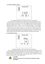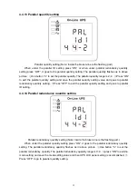
33
4.5 Parallel system commissioning
Parallel system should be commissioning when the stand-alone are all intact.
Take 4 units in parallel for example.
1)
Confirm the input/output wires connection and input phase sequence are correct; switch off the
battery breaker, and measure the +/- bat voltage of all battery group are normal.
2)
Connect the parallel cable, it should be formed loop connection.
3)
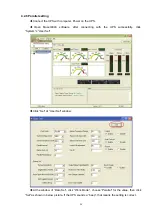
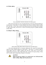
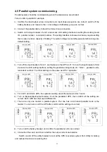
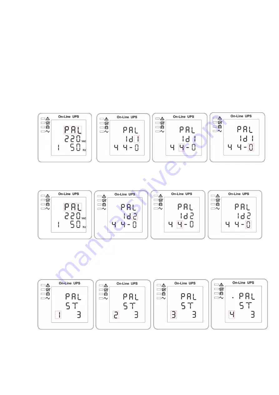
Switch on the input breaker of unit 1,and access LCD setting interface to setting the working mode
、
ID
、
parallel number
、
redundant number. The setting interface is showed as below, require setting
the in series number
、
capacity of battery. The output voltage level and Bypass protection range are
default setting.
4)
Turn off the input breaker of Unit 1, and make sure the UPS is off. Turn on the input breaker of Unit
2,access the LCD setting interface, setting the parallel working mode, ID
(
NO.2
)
, parallel 4 units,
redundant number .The other setting are the same as UPS 1 operation.
5)
For Unit 3 and Unit 4 UPS, the operation setting are all the same as Unit 1 and 2.
6)
Turn on Bypass/input/output breaker of all the paralleled UPS, then confirm all the setting are
correct. Each UPS has their owed different ID.
7)
There are only one master in parallel system .The one has a dot behind parallel mode is the
master. You can turn on all the UPS after confirm all the setting are correct.
8)
Turn on all the battery breaker and confirm the parameter (V/I) are normal.
9)
Connected the Load, and check whether the output current are balance.
Switch on and off the utility breaker to test all the UPS converters system from Utility to battery
and restored function are working find

