22
CAUTION!
Parallel cable cannot be connected when setting the parallel parameters.
◆
After setting the UPS needed to be paralleled, power off all the UPS. Connect all the UPS
according to “parallel cable installation”, and then power on the UPS
.
4.3 The LCD Display
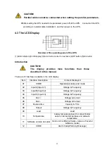
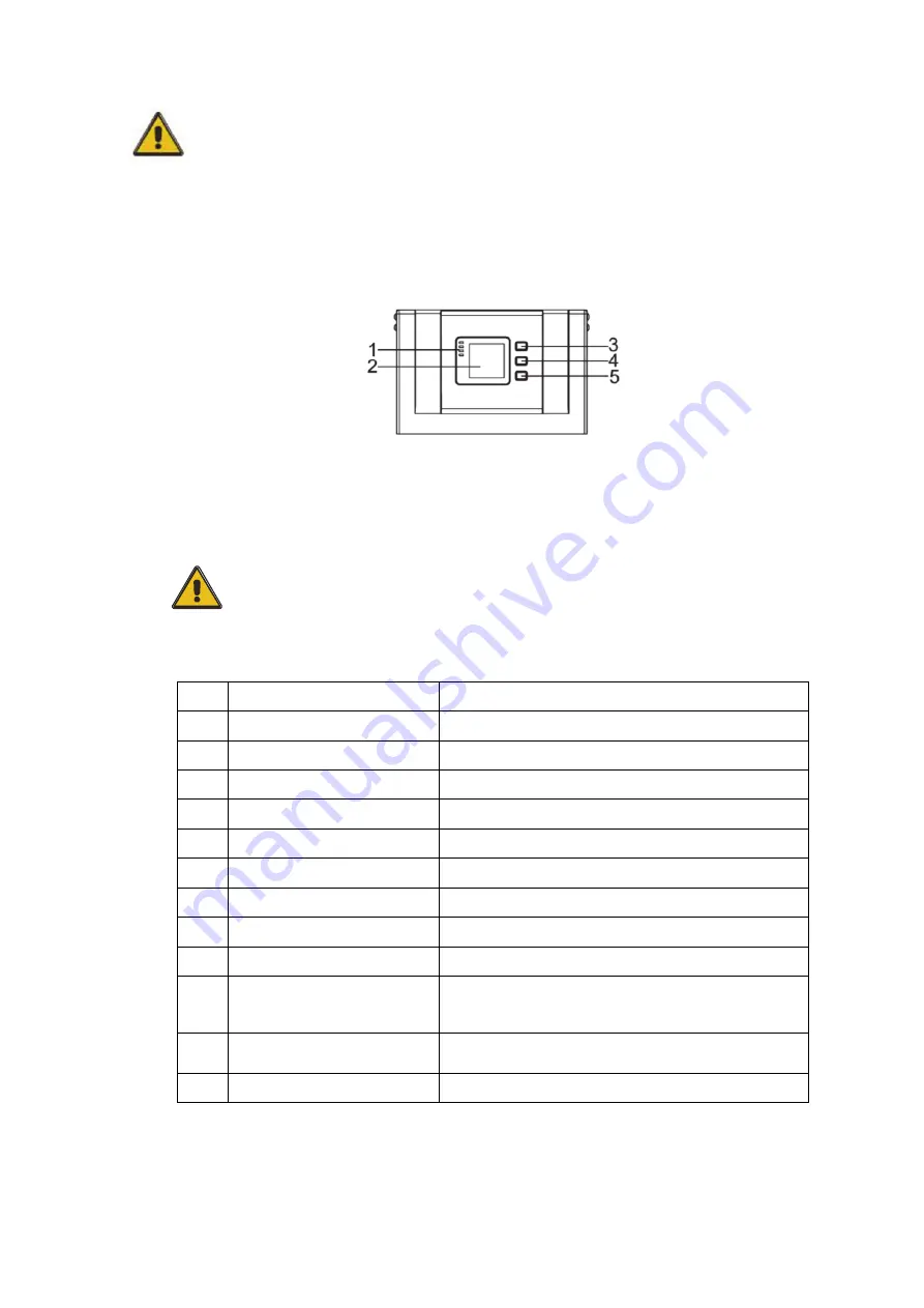
Overview of the operating panel of the UPS
(1)LED indicator (2)LCD display (3)Scroll button: enter to next item (4)Off button (5)On button
Introduction
CAUTION!
The display provides more functions than those
described in this manual.
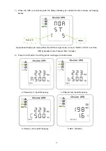
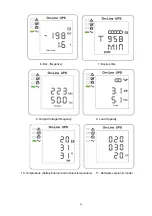
There are 12 interfaces available in the LCD display:
Item
Interface Description
Content Displayed
01
CODE
Operational status and mode
02
Input A(Input L1)
Voltage & Frequency
03
Input B(Input L2)
Voltage & Frequency
04
Input C(Input L3)
Voltage & Frequency
05
Bat. +
Voltage & Current
06
Bat. -
Voltage & Current
07
Backup time
Capacity & Time
08
Output
Voltage & Frequency
09 Load
Load
10 Temperature
battery temperature(need to connect batter
sensor, Internal temperature and ambient
temperature
11
Software version & model
Version of rectifier software, version of inverter
software, model
12
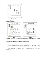
CODE
Alarm Code(Warming Message)

