background image


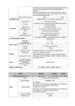
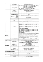
70 

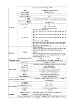
±180V/192V/±204V/±216V/±228V/±240/±252/±264/±276/±
288/±300Vdc(30/32/34/36/38/40/42/44/46/48/50pcs 
optional) 
360Vdc~600Vdc (30~50 pcs, 36 pcs define, 36 ~ 50 pcs 
no power derating; 32~34 pcs output power factor 0.9;30 
pcs output power factor 0.8;) 

charge current (A)

 max.

100A 

120A 

Transfer Time 

Utility to Battery : 0ms; Utility to bypass: 0ms 

Protection 

Short Circuit 

Hold Whole System 

Overheat 

Line Mode: Switch to Bypass; Backup Mode: Shut down 

UPS immediately 

Battery Low 

Alarm and Switch off 

Self-diagnostics 

Upon Power On and Software Control   

EPO 

Shut down UPS immediately 

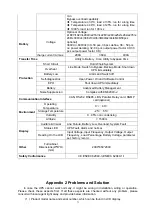
Battery   

Advanced Battery Management   

Noise Suppression 

Complies with EN62040-2 

Communication Interface


CAN, RS232, RS485, LBS, Parallel, Relay card, SNMP 

card(optional) 

Environment 

Operating 

Temperature 

0

℃~

40


Storage Temperature

-25

℃~

55


Humidity 

0

95% non condensing 

Altitude 

< 1500m 

Display 

Audible & Visual 

Line Failure, Battery Low, Overload, System Fault 

Status LED 

UPS Fault, Alarm and normal 

Reading On the LCD

Input Voltage, Input Frequency, Output Voltage, Output 
Frequency, Load Percentage, Battery Voltage, parameter 
set, history record… 

Other 

Standard cabinet 

Dimensions(W*D*H) 

600*850*1600


Full cabinet 

Dimensions(W*D*H) 

(mm) 

Safety Conformance   

CE,EN/IEC 62040-3,EN/IEC 62040-1-1 


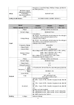
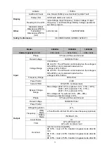
Model 

400kVA


500kVA


600kVA


Cabinet capacity 

(VA/W)


400k / 400k   

500k / 500k   

600k / 600k 

Input


Phase 

3 Phase 4 Wires and Ground 

Rated Voltage 

380/400/415Vac   

Voltage Range 

138~485Vac


  At 40°C: The UPS works at full load when the voltage is

323–485Vac and is derated load when the 
voltage is 323–138Vac 

  At 30°C: The UPS works at full load when the voltage is

305–485Vac and is derated load when the 
voltage is 305–138Vac 

Frequency Range 

40Hz-70Hz 

Power Factor 

≥0.99 

Содержание HIP3300E

Страница 1: ...t high frequency online UPS designed by our R D team who is with years of designing experiences on UPS With excellent electrical performance perfect intelligent monitoring and network functions smart...

Страница 2: ...27 3 9 1 LCD setting 27 3 9 2 LBS cable installation 27 3 9 3 UPS installation 28 4 Operation 28 4 1 Operation Modes 28 4 2 Turn on off UPS 31 4 2 1 Restart procedure 31 4 2 2 Test procedure 31 4 2 3...

Страница 3: ...spilled from the battery is strongly poisonous and do harmful to body 4 Please avoid short circuit between anode and cathode of battery otherwise it will cause spark or fire 5 Don t disassemble the UP...

Страница 4: ...e it increases reliability performance self protection and self diagnostics and so on Battery Configurable from 30 blocks to 50 blocks The battery voltage of this series UPS can be configured at 30 bl...

Страница 5: ...rance to see if the UPS is damaged or not during the transportation do not switch on the UPS if any damage found Please contact the dealer right away 3 Check the accessories according to the packing l...

Страница 6: ...5 Front View internal Front View Copper bar 200kVA 250kVA 300kVA Full configuration bottom entry Front View Side View Rear View...

Страница 7: ...6 Front View internal Front View Copper bar 400kVA Standard and Full configuration top or bottom entry Front View Side View Rear View...

Страница 8: ...7 400kVA Standard and Full configuration top entry Standard configuration Full configuration Connect copper bar...

Страница 9: ...8 400kVA Standard and Full configuration bottom entry Standard configuration Full configuration Connect copper bar...

Страница 10: ...400 500 600kVA Standard and Full configuration top and bottom entry Front View Side View Rear View 400kVA Standard and Full configuration top and bottom entry Standard configuration Full configuratio...

Страница 11: ...10 Connect coppper bar Mains bypass common copper bar 500kVA Standard and Full configuration top and bottom entry Standard configuration Full configuration...

Страница 12: ...11 Connect coppper bar Mains bypass common copper bar 600kVA Standard and Full configuration top and bottom entry Standard configuration Full configuration...

Страница 13: ...12 Connect coppper bar Mains bypass common copper bar 800 1000 1200kVA Full configuration top and bottom entry Front View...

Страница 14: ...13 Side View Rear View Full configuration...

Страница 15: ...14 Connect coppper bar Mains bypass common copper bar...

Страница 16: ...r 17 Battery positive copper bar 18 Output A input copper bar 19 Output B input copper bar 20 Output C input copper bar 21 Output neutral copper bar 22 Bypass A input copper bar Wiring must be used wh...

Страница 17: ...port MT 0V maintenance breaker auxiliary contact singnal port BP 0V bypass breaker auxiliary contact singnal port BAT 0V battery breaker auxiliary contact singnal port 3 The other port BTG 0V battery...

Страница 18: ...ort RS485 3 3 Installation notes Note Consider for the convenience of operation and maintenance the space in front and back of the cabinet should be left at least 800mm and 800mm respectively when ins...

Страница 19: ...e time required for recharging the batteries The highest altitude that UPS may work normally with full load is 1500 meters The load capacity should be reduced when this UPS is installed in place whose...

Страница 20: ...40 2 150 500 150 3 240 2 240 2 185 3 240 600 240 3 150 3 150 3 240 3 150 2 800 240 3 185 3 185 3 240 4 240 2 1000 240 4 240 4 240 4 185 6 240 3 1200 240 5 240 4 240 4 240 6 240 4 When selecting connec...

Страница 21: ...nnector Crimped OT terminals M10 10 5mm 26N m Grounding connector Crimped OT terminals M10 10 5mm 26N m 200k Mains input connector Crimped OT terminals M10 10 5mm 26N m Bypass input connector Crimped...

Страница 22: ...rimped OT terminals M12 13 5mm 35N m Grounding connector Crimped OT terminals M12 13 5mm 35N m 600k Mains input connector Crimped OT terminals M12 13 5mm 35N m Bypass input connector Crimped OT termin...

Страница 23: ...100k Mains input circuit breaker 200A 3P Bypass input circuit breaker 200A 3P Output circuit breaker r 200A 3P Battery circuit breaker 320A 3P 120k Mains input circuit breaker 250A 3P Bypass input cir...

Страница 24: ...circuit breaker 2500A 3P 1000k Mains input circuit breaker 2000A 3P Bypass input circuit breaker 1600A 3P Output circuit breaker 1600A 3P Battery circuit breaker 3200A 3P 1200k Mains input circuit bre...

Страница 25: ...on the arrival of the commissioning engineer then ensure that the system output cables are safely isolated at their ends Connect the safety earth and any necessary bonding earth cables to the copper...

Страница 26: ...the long run unit is battery quantity 36pcs battery capacity 12V 100AH When connecting 30 32 34 36 38 42 44 46 48 50 batteries please re set desired battery quantity and its capacity after UPS starts...

Страница 27: ...he relevant wiring rules the following requirements should be met All UPS must be the same rated and connected to the same way bypass power supply Bypass and the mains input power must be received wit...

Страница 28: ...setting Set every UPS of the systems to be LBS Master or LBS Slave For instance if the UPS belongs to LBS master system its LBS setting must be set to Master 3 9 2 LBS cable installation The two ports...

Страница 29: ...28 3 9 3 UPS installation The whole systems are showed below 4 Operation 4 1 Operation Modes...

Страница 30: ...neously Then the inverter converts the DC power to AC and supplies to the load Battery mode Stored Energy Mode If the AC mains input power fails the inverter which obtains power from the battery suppl...

Страница 31: ...on is programmable but typically set to be less than an electrical cycle e g less than 15ms 50Hz or less than 13 33ms 60Hz ECO Mode When the UPS is at AC Mode and the requirement to the load is not cr...

Страница 32: ...UPS make sure that Bypass module insert the cabinet and fix with screws and the module_in switch at the on status When AC MAINS input voltage within the range and the rectifiers of the UPS will be sta...

Страница 33: ...normal rectifier starts operation 30s later inverter starts and operates and the green LED will light on CAUTION Wait for approximately 30 seconds before you press the black start key 4 2 4 MAINTENAN...

Страница 34: ...power switches isolators and circuit breakers are opened there will be no output Press the INVERTER OFF key on the LCD display Switch OFF the BATTERY switch Open the UPS door to easily access to the...

Страница 35: ...l Note The UPS cannot be parallel until each single unit is normal 4 3 The Display 4 3 1 Datas Displays the flow state of UPS work and quickly enters real time data by clicking on the block Power rate...

Страница 36: ...rough by real time data block view the status of the switches dry contacts through clicking on the block enter the corresponding data window 4 3 2 1 Main Click the main block to enter the main data di...

Страница 37: ...splay window click return to return to the previous window click home page to return to the main page 4 3 2 3 Output Click the output block to enter the output data display window click return to retu...

Страница 38: ...37 4 3 2 4 Battery Click the battery block to enter the battery data display window click return to return to the previous window click home page to return to the main page...

Страница 39: ...38 4 3 2 5 Status info Click the status info block to enter the status data display window click return to return to the previous window click home page to return to the main page...

Страница 40: ...39...

Страница 41: ...40 4 3 3 Alarm View the alarm and history of the UPS and open or close the buzer...

Страница 42: ...display window click return to return to the previous window click home page to return to the main page 4 3 3 2 History Click the history to enter the history recode display window click return to ret...

Страница 43: ...hen the buzzer will mute and the red block will change to green if the buzzer is on then click the block buzzer will on and the block will change to red click return to return to the previous window c...

Страница 44: ...43 4 3 4 Setting There are two levels the basic setting for user settings advanced setting for technical personnel please contact the relevant technical personnel to enter advanced settings...

Страница 45: ...44 4 3 4 1 Basic Setting Click basic setting enter by input the correct password The user password is 111111...

Страница 46: ...Password Click password block enter user password setting page input old password and new password then click save confir to save the change Password format is six number click return to return to th...

Страница 47: ...and click the save config block to save Value range is 1 63 default value is 63 Click return to return to the previous window click home page to return to the main page Backlight time LCD backlight de...

Страница 48: ...1 5 Communication setting Click the text to select other value or input new value and click save config block to save Click return to return to the previous window click home page to return to the mai...

Страница 49: ...48...

Страница 50: ...PS start logic Enable UPS start inverter output automatic Disable No output Aging Load Rate The value can be 18 100 default value 60 Rreq Conv Mode Frequency conversion mode enable output frequency se...

Страница 51: ...or power grid The value can be 0 200 default value is 10 Inter sleep mode when load less than the software setting value same parallel rack will turn to standby mode and if the load more than the sett...

Страница 52: ...5 default value is 0 Output Freq Output frequency The value can be 50Hz or 60Hz Output Volt Level Output voltage level The value can be 220V 230V 240V Output Ivn Volt Regu Inverter voltage regulated T...

Страница 53: ...battery capacity The value can be 0 05 0 15 and is 0 1 by default Cell float voltage The float voltage value can be 2 23 2 30 V cell and is 2 25 V cell by default Cell boost voltage The battery equali...

Страница 54: ...tow parallel ups use common batter bank The value can be set share battery pack or Not shared battery P not shared battery P by default Generator on prohibit charging UPS disable charge the battery if...

Страница 55: ...his value the system determines that the bypass frequency is not normal and that the bypass is unavailable The value range is 1 2 4 5 10 default Bypass rate tracking rate Inverter frequency tracking t...

Страница 56: ...utput The default value is Disable External Maint breaker Enable or disable external maintenance breaker connection detection The default value is Disable Battery Switch Enable or disable battery brea...

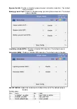
Страница 57: ...fault value is Disable Lightning arrester SPD Enable or disable SPD detection The default value is Disable Generator GEN Enable or disable GEN detection The default value is Disable OUT01 OUT06 Output...

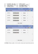
Страница 58: ...W_VOLT 11 MAINT_CLOSE 5 BATTERY_SELFCHECK 12 OIL_MACHINE_CONTROL 6 MAIN_SUPPLY 13 SYS_MAINT_OPEN 7 BYPASS_SUPPLY 14 SYS_OUPPUT_OPEN 4 3 5 Maint Software update Touch corrention history download and ba...

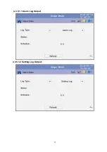
Страница 59: ...58 4 3 5 1 USB Wizard History Output download history and setting record by USB...

Страница 60: ...59 4 3 5 1 1 Alarm Log Output 4 3 5 1 2 Setting Log Output...

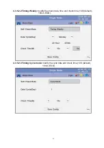
Страница 61: ...Battery Self Check can select check by Timing Daily Timing Weekly Cycle mode The default value is Timing Self Check Close 4 3 5 2 1 Timing Daily modify the check date time and check time 10S default...

Страница 62: ...61 4 3 5 2 2 Timing Weekly modify the check date time and check time 10S default 10min EOD 4 3 5 2 3 Timing Cycle mode modify the cycle date and check time 10S default 10min EOD...

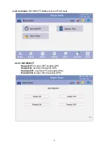
Страница 63: ...INV ON OFF Battery test and Fault clear 4 3 6 1 INV ON OFF Single OFF Inverter OFF location UPS Single ON Inverter ON location UPS Parallel OFF Inverter OFF all parallel UPSs Parallel ON Inverter ON a...

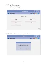
Страница 64: ...63 4 3 6 2 Battery Test 10S battery test for 10s 10min battery test for 10min EOD battery test to EOD 10 battery test down 10 capability 4 3 6 3 Fault clear Clear the current fault not for all faults...

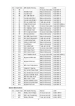
Страница 65: ...Over Current Beep continuously Fault LED lit 4 5 REC Power Fault Beep continuously Fault LED lit 5 7 Input SCR Fault Beep continuously Fault LED lit 6 10 Battery SCR Fault Beep continuously Fault LED...

Страница 66: ...lt LED lit 35 134 ECU Insert Fault Once per 2 seconds Fault LED lit 36 136 ECU Power Fault Beep continuously Fault LED lit 37 139 ECU Comm Fault Beep continuously Fault LED lit 38 141 ECU Initializes...

Страница 67: ...2 seconds Alarm LED lit 21 323 Parallel Overload Once per 2 seconds Alarm LED lit 22 324 Bypass Overload Once per 2 seconds Alarm LED lit 23 325 Maint Switch Misuse Once per 2 seconds Alarm LED lit 24...

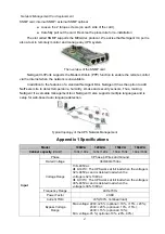
Страница 68: ...urity sensors Thus making NetAgent II a versatile management tool NetAgent II also supports multiple languages and is setup for web based auto language detection Typical topology of the UPS Network Ma...

Страница 69: ...0 42 44 46 48 50pcs optional 360Vdc 600Vdc 30 50 pcs 36 pcs define 36 50 pcs no power derating 32 34 pcs output power factor 0 9 30 pcs output power factor 0 8 charge current A max 40A 60A Transfer Ti...

Страница 70: ...Power Factor 0 99 Current THDi 3 100 nonlinear load Bypass Voltage Range Max voltage 220V 25 optional 10 15 20 230V 20 optional 10 15 240V 15 optional 10 Min voltage 45 optional 10 20 30 Frequency pr...

Страница 71: ...ting Temperature 0 40 Storage Temperature 25 55 Humidity 0 95 non condensing Altitude 1500m Display Audible Visual Line Failure Battery Low Overload System Fault Status LED UPS Fault Alarm and normal...

Страница 72: ...time Temperature 40 C load 125 run for a long time 1000 load run for 100 ms Battery Voltage Optional Voltage 180V 192V 204V 216V 228V 240 252 264 276 288 300Vdc 30 32 34 36 38 40 42 44 46 48 50pcs opt...

Страница 73: ...Vac and is derated load when the voltage is 323 138Vac At 30 C The UPS works at full load when the voltage is 305 485Vac and is derated load when the voltage is 305 138Vac Frequency Range 40Hz 70Hz Po...

Страница 74: ...ry Management Noise Suppression Complies with EN62040 2 Communication Interface CAN RS232 RS485 LBS Parallel Relay card SNMP card optional Environment Operating Temperature 0 40 Storage Temperature 25...

Страница 75: ...D is flashing Utility voltage exceeds UPS input range If the UPS operates at battery mode please pay attention to the remaining backup time needed for your system 8 Battery LED is flashing but no char...

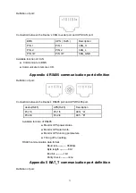
Страница 76: ...tion port definition Definition of port Connection between the Device s RS485 port and UPS RS485 port device RJ45 UPS RJ45 Description Pin 1 5 Pin 1 5 485 A Pin 2 4 Pin 2 4 485 B Available function of...

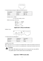
Страница 77: ...Definition of port Connection between the UPS LBS port UPS RJ45 UPS RJ45 Description Pin 1 2 3 Pin 1 2 3 LBS Pin 5 7 8 Pin 5 7 8 GND Available function of LBS The output power of two or more UPS in n...

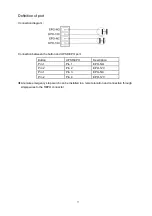
Страница 78: ...he button and UPS REPO port Button UPS REPO Description Pin 1 Pin 1 EPO NO Pin 2 Pin 2 EPO 12V Pin 1 Pin 3 EPO NC Pin 2 Pin 4 EPO 12V A remote emergency stop switch can be installed in a remote locati...

Отзывы: