background image

9 Related Documents

43 of 52

KSB SuPremE

914.19

900

900.04

914.14

914.07
930.07

421.01

950

903

81-36

914.01

99-9.02

831

914.52 
930.52

832

UG1492278

360.02

914.02 

970.02

932.01

321.02

421.02

932.02

835

81-22

914.06
930.06

80-1

930.18

914.18

360.01

550

836

99-9.01

818

321.01

940

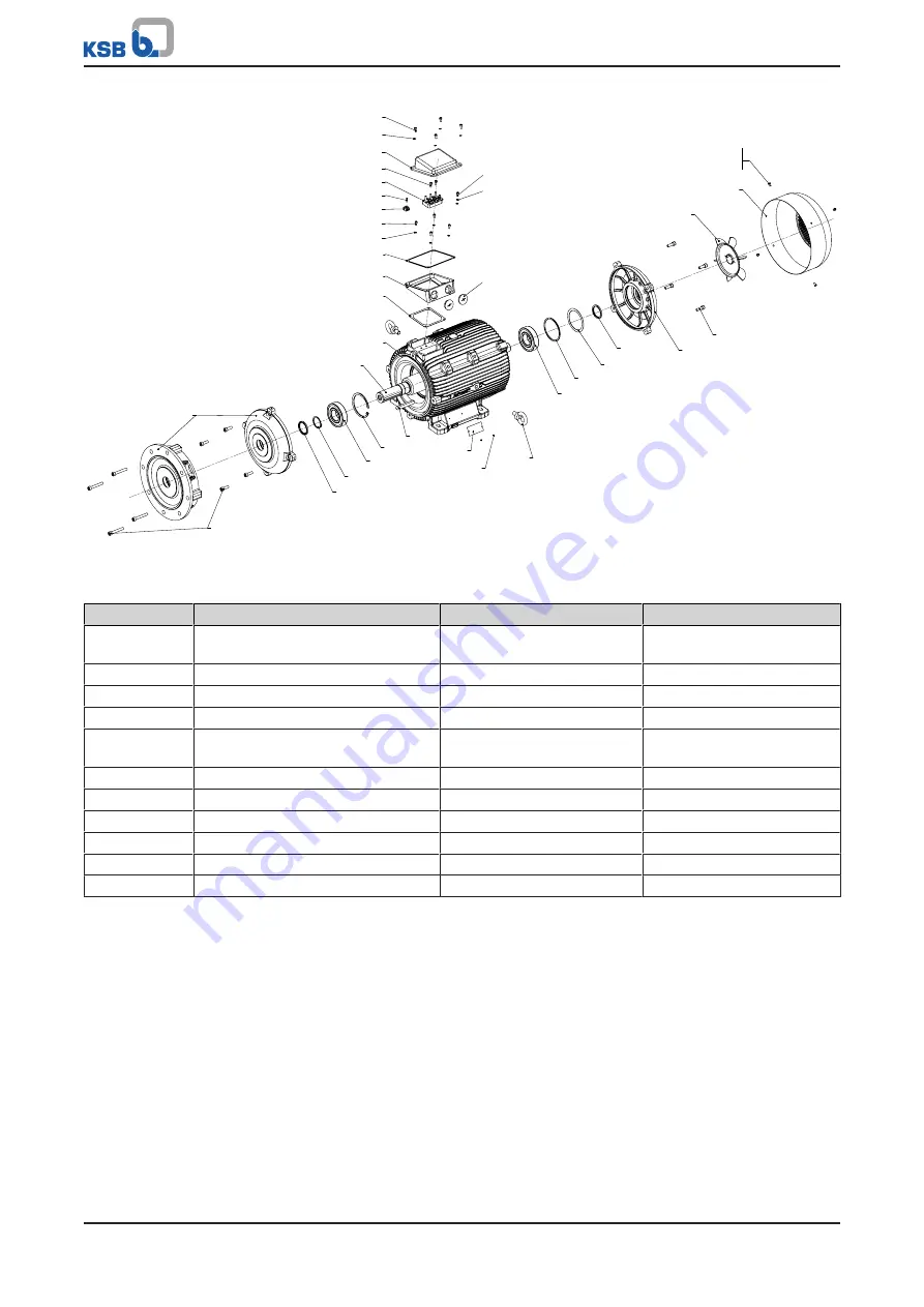
Fig. 8: 

Variant made of grey cast iron

Table 28: 

List of components

Part No.

Description

Part No.

Description

80-1

Motor unit (motor housing with
stator)

835

Terminal board

81-22

Terminal box cover

836

Terminal strip

81-36

Terminal box base

900.04

Bolt/screw

99-9.01/.02

Set of sealing elements

903

Screw plug

321.01/.02

Radial ball bearing

914.01/.02/.06/.07/.14/.18/.19/.
52

Hexagon socket head cap
screw

360.01/.02

Bearing cover

930.06/.07/.18/.52

Safety device

421.01/.02

Lip seal

932.01/.02

Circlip

550

Disc

940

Key

818

Rotor

950

Spring

831

Fan impeller

970.02

Name plate

832

Fan hood

Содержание SuPreme Series

Страница 1: ...Synchronous Reluctance Motor KSB SuPremE Installation Operating Manual ...

Страница 2: ...tents provided herein must neither be distributed copied reproduced edited or processed for any other purpose nor otherwise transmitted published or made available to a third party without the manufacturer s express written consent Subject to technical modification without prior notice KSB SE Co KGaA Frankenthal 06 03 2019 ...

Страница 3: ...ption 12 4 1 General description 12 4 2 Designation 12 4 3 Name plate 13 4 4 Technical data 15 4 5 Types of construction 15 4 6 Mounting arrangements 16 4 7 Noise characteristics 18 4 8 Balancing 19 5 Installation at Site 20 5 1 Safety regulations 20 5 2 Checks to be carried out prior to installation 20 5 3 Installing the motor or electric drive 21 5 4 Electrical connection 23 5 4 1 Version with t...

Страница 4: ...antling the fan 37 7 3 5 Dismantling the rotor 37 7 3 6 Dismantling the bearings 37 7 4 Assembling the motor 38 7 4 1 Fitting the bearings 38 7 4 2 Installing the rotor 39 7 4 3 Mounting the fan 39 7 4 4 Mounting the fan hood 39 7 4 5 Mounting the protective roof optional 39 8 Troubleshooting 40 9 Related Documents 42 9 1 General assembly drawing with list of components 42 10 EU Declaration of Con...

Страница 5: ...hine element IE4 Efficiency class to IEC TS 60034 30 2 2016 Super Premium Efficiency IE International Efficiency IE5 Efficiency class to IEC TS 60034 30 2 2016 Ultra Premium Efficiency IE International Efficiency Motor Device that performs mechanical work by converting different forms of energy e g electrical energy into kinetic energy Non drive end End of motor with fan and fan hood ...

Страница 6: ...perating manual Proper and safe use of the pump in all phases of operation Operating manual for PumpDrive 2 and PumpDrive R Proper and safe use of PumpDrive in all phases of operation Wiring diagram Electrical connection For accessories and or integrated machinery components observe the relevant manufacturer s product literature 1 4 Symbols Table 2 Symbols used in this manual Symbol Description Co...

Страница 7: ...f the signal words this symbol indicates a hazard which will or could result in death or serious injury Electrical hazard In conjunction with one of the signal words this symbol indicates a hazard involving electrical voltage and identifies information about protection against electrical voltage Machine damage In conjunction with the signal word CAUTION this symbol indicates a hazard for the machi...

Страница 8: ...for the mains voltage mains frequency ambient temperature motor rating speed density pressure temperature and in compliance with any other instructions provided in the operating manual or other applicable documents The product must not be used in potentially explosive atmospheres 2 3 Personnel qualification and training All personnel involved must be fully qualified to install operate maintain and...

Страница 9: ... Use only original spare parts or parts components authorised by the manufacturer The use of other parts components can invalidate any liability of the manufacturer for resulting damage The operator ensures that maintenance inspection and installation are performed by authorised qualified specialist personnel who are thoroughly familiar with the manual Any work on the product shall only be perform...

Страница 10: ...cks for additional transport tasks or re enable To transport the motor suspend it from the lifting tackle as shown Transporting the motor by two lifting lugs attached to sides of motor housing Transporting the motor by one lifting lug attached to top of motor housing 3 3 Storage preservation Exposed machined metal surfaces Exposed locating surfaces shaft ends flange faces centring spigots connecto...

Страница 11: ...ge Storage rooms should provide protection against extreme weather conditions and be dry dust free frost free jolt free vibration free and well ventilated Storage of motors of type of construction X2 with mounting plate for PumpDrive 2 For storing a motor of this type of construction please note that when the frequency inverter is not mounted the motor s enclosure is IP40 Protect the connection pr...

Страница 12: ... PN kW 0 55 0 55 45 0 45 00 9 12 Motor size 71M Shaft centreline height mm 225M Shaft centreline height mm 14 Enclosure B IP55 or IP40 55 15 Type of protection W Non explosionproof 16 Electrical voltage A P 3 AC 220 VΔ 380 VY 50 Hz 17 Efficiency class 7 IE4 IE5 NEMA Super Premium Ultra Premium 18 Thermal class F Thermal class 155 F 19 Motor protection winding protection 3 3 PTC thermistors 20 Dire...

Страница 13: ...SB SuPremE B vermilion RAL 2002 KSH KSB SuPremE B ultramarine blue RAL 5002 SCD KSB SuPremE C pearl gold RAL 1036 SCD KSB SuPremE C ultramarine blue RAL 5002 4 3 Name plate IE 5 159 kg Th Cl 155 F IP55 20 C TAMB 40 C Converter Duty Only VPWM V Hz A kW cos φ Nm 1 min 380 Y 100 50 22 0 0 71 70 3000 01634340 Nmax 4200 1 min 1 2 3 4 5 6 7 8 9 10 11 12 13 14 15 16 17 18 19 20 KSB SE Co KGaA 67227 Frank...

Страница 14: ... 52 KSB SuPremE 13 Power factor no effect on power supply network 14 Rated power 15 Rated current 16 KSB material number 17 Rated frequency 18 Rated voltage for the supplying frequency inverter 19 Thermal class 20 Weight ...

Страница 15: ...P552 Paint coat RAL 5002 RAL 1036 or if combined with a pump in the same colour as the pump 4 5 Types of construction The motors are available in different types of construction KSB SuPremE X1 With terminal box for connecting to PumpDrive 2 or PumpDrive R for mounting on walls and in control cabinets KSB SuPremE X2 Equipped for being fitted with a motor mounted PumpDrive 2 Table 7 Designs Flange t...

Страница 16: ...m Mounting arrangement IM Flange with tapped holes FT 6 132 V18 4 B14 V19 4 6 Mounting arrangements Table 8 Mounting arrangement for B3 Standard mounting arrangement Further mounting arrangements Shaft centreline height mm H 160 H 180 IM B3 IM B6 IM B7 IM B8 IM V5 6 Special design for Movitec ...

Страница 17: ...nting arrangements for V15 Standard mounting arrangement Further mounting arrangements Shaft centreline height mm H 160 H 180 IM V15 IM V35 IM B35 Table 10 Mounting arrangements for V1 Standard mounting arrangement Further mounting arrangements Shaft centreline height mm H 160 H 180 IM V1 IM V3 7 7 Feet can be removed from IM V15 basic type of construction ...

Страница 18: ...gements Shaft centreline height mm H 132 IM V18 IM B14 IM V19 4 7 Noise characteristics Table 12 Sound pressure level LpA Rated speed Rated power Motor size Sound pressure level LpA 8 rpm kW dB A 1500 0 55 80M 60 1500 0 75 80M 60 1500 1 1 90S 60 1500 1 5 90L 60 1500 2 2 100L 60 1500 3 100L 60 1500 4 112M 61 1500 5 5 132S 61 1500 7 5 132M 61 1500 11 160M 61 1500 15 160L 61 1500 18 5 180M 63 1500 22...

Страница 19: ... 3000 18 5 160L 72 3000 22 180M 72 3000 30 200L 72 3000 37 200L 72 3000 45 225M 72 4 8 Balancing The rotor is balanced dynamically in accordance with DIN ISO 21940 11 The rotor is balanced to balance quality grade G 2 5 Marking For motors with key the rotors are balanced dynamically with a half key H as standard in accordance with ISO 21940 32 requirements The output element must also be balanced ...

Страница 20: ...to be carried out prior to installation Place of installation WARNING Installation on mounting surface which is unsecured and cannot support the load Personal injury and damage to property Use a concrete of compressive strength class C12 15 which meets the requirements of exposure class XC1 to EN 206 1 The mounting surface must be set flat and level Observe the weights indicated 1 Check the struct...

Страница 21: ...lation Drive overheated Maintain the specified minimum distances to neighbouring assemblies Never restrict the ventilation ducting to from the drive Prevent exhaust air from neighbouring assemblies from being drawn in directly X Fig 2 Minimum distance X Table 14 Minimum distance X to neighbouring assemblies Motors with shaft centreline height mm Minimum distance X mm 71 100 30 112 132 40 160 180 5...

Страница 22: ...ning For horizontal positioning laterally shift the drive on the foundation while maintaining axial alignment to prevent angular misalignment Ensure a uniform circumferential axial clearance at the coupling when positioning Smooth running characteristics A stable vibration free foundation to DIN 4024 exact alignment of the coupling and a well balanced output element coupling pulley fan etc are pre...

Страница 23: ...nting 5 4 1 Version with terminal box Observe the following when performing any work on the terminal box Always use the original seal to close the terminal box so that it is dust and watertight Do not damage components on the inside of the terminal box e g terminal board and cable connections Ensure that no foreign bodies contamination or moisture are present in the terminal box Terminal box cable...

Страница 24: ...ar configuration Terminals U2 V2 and W2 are not connected Connect the motor terminals U1 V1 and W1 to terminals U V and W of the relevant frequency inverter 4 Connect the earth conductor PE Table 16 Compatible conductor cross section Motor size Max compatible conductor cross section mm 71M 80M 4 90S 160M 6 160L 16 180M L 25 200L 225M 50 Table 17 Bolt size of earth conductor PE Shaft centreline hei...

Страница 25: ...the direction of the fan hood U1 V1 W1 PTC 1 PE PTC 2 Fig 5 Pin assignment of the connector KSB SuPremE X2 5 5 kW and higher The mounting plate of units rated for 5 5 kW or higher has a cable gland for the phase conductors and the earth conductor plus 2 PTC connection wires These are directly connected in the terminal wiring compartment of PumpDrive 2 according to their marking or colour coding Ta...

Страница 26: ...For cable glands made from metal and plastic for establishing a direct connection to a drive and for other glands e g reducers refer to the following table to apply the correct tightening torques Table 20 Bolt screw sizes and tightening torques for the electrical connection Shaft centreline height Terminal box terminal box cover Terminal board connections Terminal board fastening Earth conductor c...

Страница 27: ...rque Nm 6 6 6 3 100 Thread M6 M5 M5 M4 Tightening torque Nm 10 6 6 3 112 Thread M8 M5 M5 M4 Tightening torque Nm 23 6 6 3 132 Thread M8 M5 M6 M6 Tightening torque Nm 23 6 10 10 160 Thread M10 M6 M8 M40 x 1 5 M6 M8 Tightening torque Nm 46 10 23 8 10 23 180 Thread M10 M6 M6 M40 x 1 5 M8 Tightening torque Nm 46 10 10 8 23 200 Thread M12 M6 M8 M40 x 1 5 M8 Tightening torque Nm 80 10 23 8 23 225 Thread...

Страница 28: ...sulation resistance after a long operating time 0 5 MΩ kV The insulation resistance can be optimally measured at 25 C If the measurement is taken at 25 C the measurement result must be converted to the reference value at 25 C so that a comparison can be made with the data in the table above The insulation resistance halves for every 10 C increase in temperature The insulation resistance doubles fo...

Страница 29: ...k that the drive is connected correctly for the specified direction of rotation Make sure that the operating conditions correspond to the data specified on the name plate Make sure that the output elements are correctly configured depending on type e g alignment and balancing of couplings belt forces for belt drive tooth forces and tooth flank clearance for gearwheel drive radial and axial clearan...

Страница 30: ...r For motors with a transport lock remove the lock prior to turning the rotor Before you start the drive read the information in section Returning to service ð Section 6 2 Page 29 If you plan to take the drive out of service for more than 12 months implement appropriate corrosion protection preservation packaging and drying measures 6 6 Returning to service NOTE Returning to service only in conjun...

Страница 31: ...til dangerous voltages have discharged Ensure that the drive cannot be started unintentionally WARNING Insufficient stability Risk of crushing hands and feet During assembly dismantling secure the drive against tilting or tipping over A regular maintenance schedule will help avoid expensive repairs and contribute to trouble free reliable operation of the drive with a minimum of maintenance expendi...

Страница 32: ...urns Never touch a motor when it is in operation Let the motor cool down Only remove covers if indicated WARNING Condensing air humidity inside the motor if the motor and or ambient temperatures frequently change Risk of corrosion by condensation Always observe the information provided on ambient conditions While the system is in operation observe and check the following Deviations from normal ope...

Страница 33: ...n the foundation Immediately correct impermissible deviations that are detected during inspection work NOTE Further inspections tests are required in accordance with the additional operating manuals or the particular system specific conditions General inspection Inspection interval Once annually Procedure Check the following during operation The specified electrical characteristics are complied wi...

Страница 34: ...ication and lubricant change 7 2 2 3 1 Maintenance of rolling element bearings Maintenance of rolling element bearings after an extended storage period Extended storage periods decrease the service life of the lubricating grease This in turn reduces the service life of the bearings The rolling element bearings should be completely replaced after a storage period of more than 4 years After a storag...

Страница 35: ...d every 2000 hours If the motor is operated under extreme conditions such as vibrations or high temperatures the bearings must be re lubricated more frequently 7 2 2 3 2 Re lubrication DANGER Excessive temperatures as a result of bearings running hot or defective bearing seals Fire hazard Damage to the motor Regularly check the condition of the lubricant Regularly check the rolling element bearing...

Страница 36: ...ng 7 3 Dismantling the motor 7 3 1 General information Safety regulations DANGER Hot surface Risk of burns Never touch a motor when it is in operation Let the motor cool down Only remove covers if indicated WARNING Improper lifting moving of heavy assemblies or components Personal injury and damage to property Use suitable transport devices lifting equipment and lifting tackle to move heavy assemb...

Страница 37: ...lable 1 Remove non drive end and drive end keys and store them in a safe place 2 Remove the bolts from the drive end bearing cover 3 Stand the motor housing upright drive end up pull the bearing cover and rotor out of the motor housing using suitable lifting equipment and place them down as illustrated in the drawing 7 3 6 Dismantling the bearings Fixed bearing at drive end ü The rotor has been di...

Страница 38: ...the corresponding exploded view Clean all dismantled components and check them for signs of wear Damaged or worn components must be replaced by new ones Always use new tolerance rings Make sure that sealing surfaces are clean and that O rings or gaskets are properly fitted Tightening torques For reassembly tighten all screws and bolts as specified in this manual 7 4 1 Fitting the bearings CAUTION ...

Страница 39: ...ht drive end up and guide the bearing cover and rotor into the motor housing using suitable lifting equipment 3 Tighten the bolts on the drive end bearing cover ð Section 5 5 Page 26 4 Insert non drive end key 7 4 3 Mounting the fan 1 Fit the fan 2 Fit clamping screws or circlip depending on size 7 4 4 Mounting the fan hood 1 Position fan hood and affix with bolts ð Section 5 5 Page 26 7 4 5 Mount...

Страница 40: ...ables connected incorrectly Fault in supply line Check wiring Mains fuse rating too small for frequency inverter input current Observe connected loads from the project planning information for the frequency inverter and observe VDE 0100 requirements Permissible voltage range undershot exceeded Check output voltage of frequency inverter and operate drive using required voltage No enable Insert brid...

Страница 41: ...point system specific Check the permissible load and if necessary use external cooling Damage to the bearings Check bearings and replace if necessary Rubbing contact between rotor and stator Check bearings and replace if necessary Check rotor and replace if necessary Rotor unbalance Check key convention applicable to the shaft and output element remove rotor and re balance if required Improper ins...

Страница 42: ...Fig 7 Variant made of aluminium Table 27 List of components Part No Description Part No Description 80 1 Motor unit motor housing with stator 833 Terminal box 81 23 Motor foot 835 Terminal board 99 9 01 02 Set of sealing elements 900 15 Bolt screw 321 Radial ball bearing 903 Screw plug 360 Bearing cover 914 01 02 03 05 07 09 10 Hexagon socket head cap screw 421 Lip seal 920 01 02 05 Nut 550 Disc 9...

Страница 43: ...28 List of components Part No Description Part No Description 80 1 Motor unit motor housing with stator 835 Terminal board 81 22 Terminal box cover 836 Terminal strip 81 36 Terminal box base 900 04 Bolt screw 99 9 01 02 Set of sealing elements 903 Screw plug 321 01 02 Radial ball bearing 914 01 02 06 07 14 18 19 52 Hexagon socket head cap screw 360 01 02 Bearing cover 930 06 07 18 52 Safety device...

Страница 44: ...92488 900 11 550 11 400 900 13 930 12 914 16 81 2 Fig 9 Adapter sizes A and B Table 29 List of components Part No Description Part No Description 81 2 Plug 595 11 Buffer 82 5 Adapter 900 11 13 Bolt screw 400 Gasket 914 12 16 Hexagon socket head cap screw 550 11 Disc 930 12 Safety device ...

Страница 45: ...2 UG1492488 900 11 920 400 900 13 930 12 826 Fig 10 Adapter size C Table 30 List of components Part No Description Part No Description 82 5 Adapter 900 11 13 Bolt screw 400 Gasket 914 12 Hexagon socket head cap screw 595 11 Buffer 920 Nut 826 Cable gland 930 12 Safety device ...

Страница 46: ...le 31 List of components Part No Description Part No Description 81 7411 Pressure screw 913 Pressure balancing element 82 5 Adapter 914 11 12 Hexagon socket head cap screw 40012 Gasket 930 12 Safety device 900 11 1311 Bolt screw 11 Not when using an adapter with pressure balancing element 12 Only when using an adapter with pressure balancing element ...

Страница 47: ...ity with the provisions of the following Directives as amended from time to time Motor Low voltage Directive 2014 35 EU The manufacturer also declares that the following harmonised international standards have been applied EN 50347 Applied national technical standards and specifications in particular EN 60034 VDE 0530 The product must not be put into service for its intended use until the final pr...

Страница 48: ...40 I Installation at site 20 Intended use 8 K Key to safety symbols markings 6 M Maintenance work 31 N Name plate 13 O Other applicable documents 6 P Personnel 8 Product code 12 Q Qualification 8 R Returning to service 30 S Safety 8 Safety awareness 9 Servicing Maintenance 31 Specialist personnel 8 T Technical data 15 Training 8 Transport 10 W Warnings 6 Warranty claims 6 ...

Страница 49: ......

Страница 50: ......

Страница 51: ......

Страница 52: ...KSB SE Co KGaA Johann Klein Straße 9 67227 Frankenthal Germany Tel 49 6233 86 0 www ksb com 4075 85 06 EN 01645879 ...

Отзывы: