background image

MDX [en-US] 

39 


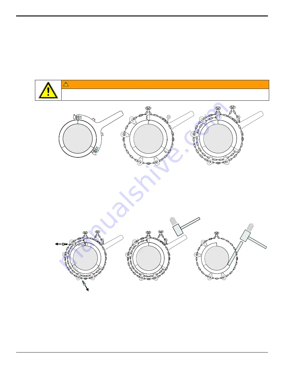
Screw the two SHCS that come with the tool into the push off holes finger tight. 


Tighten the tab bolts with a wrench while pushing the tabs into the IRR grooves. 


Tighten the SHCS that hold the tool to the IRR. 


Screw in four lifting eyes (finger tight) into the push off holes in the remaining IRR segments until they bottom against 
the shaft. 


Screw a lifting eye in the tool. Note: some tools already have an eye welded to the tool, so a screw-in lifting eye is not 
required. 


Thread one chain through the four lifting eyes and around the shaft. Remove the slack in the chain and connect the 
ends of the chain with a carabineer. 


Thread a second chain through the tool lifting eye and around the shaft. 


 WARNING 

The chains are required as a safety precaution and must be used to prevent injury. 


Remove the slack in the chain and connect the ends of the chain with a carabineer. 


Remove the remaining two IRR parting line SHCS. Note: it may be necessary to move the nearby lifting eye first. 


Hit the tool with a sledge hammer until the IRR segment breaks free. After each hammer blow, re-tighten any loose 
fasteners and verify the tabs fit snugly into the IRR groove. 


If all three IRR segments break loose, the removal job is complete. Otherwise, remove the tool, the loose IRR segment 
and the chain. While the other two IRR segments are still chained to the shaft, seat a solid steel bar on the parting line 
face of either of the two remaining segments, and rap with a hammer until they break free. 


Содержание GIW MDX

Страница 1: ...ring replacement parts This is a standard maintenance manual provided for your convenience This manual may include additional documentation not applicable to your specific pump GIW INDUSTRIES INC 5000...

Страница 2: ...nal operating manual the original operating manual prevails All rights reserved Contents provided herein must neither be distributed copied reproduced edited or processed for any other purpose nor oth...

Страница 3: ...Strainer 22 6 2 Start up 22 6 2 1 Priming the Pump 22 6 3 Shutdown 23 6 3 1 Measures to be taken for Prolonged Shutdown 23 6 4 Operating Limits 23 6 4 1 Temperature Limits 23 6 4 2 Switching Frequenc...

Страница 4: ...ngs 29 Noise Characteristics 14 Nose Gap Adjustment 47 Oil Temperature Monitoring 19 Operating Conditions of Flow and Head 27 Operating Limits 23 Operation 20 Operation Unauthorized Modes 7 Operationa...

Страница 5: ...he medium handled capacity speed density pressure temperature and motor rating Make sure that operation is in accordance with the instructions given in this manual or in the contract documentation The...

Страница 6: ...ordance with EC Directive 94 9 EC ATEX General hazard In conjunction with one of the signal words this symbol indicates a hazard which will or could result in death or serious injury Electrical hazard...

Страница 7: ...red to without fail Pumps or pump units handling media injurious to health must be decontaminated Immediately following completion of the work all safety protective devices must be re installed and or...

Страница 8: ...in personal injury and damage to equipment Work on the unit must only be carried out with the electrical connections disconnected and locked out Make sure that the pump set cannot be switched on accid...

Страница 9: ...mps ensure that the unit remains in the horizontal position during lifting and cannot slip out of the suspension arrangement Ensure that the pump is firmly strapped down during shipment Pump should be...

Страница 10: ...eather or other vent added to the bearing housing o Vertical pumps should be stored horizontally and filled with Storage Oil to the center of the sight glass or 25mm 1 inch below the largest diameter...

Страница 11: ...life is 5 years Keep dry out of direct sunlight or other UV ultraviolet sources and away from heat Store in the box with part being covered with the black plastic low density polyethylene bags 4mil 0...

Страница 12: ...replaced prior to commissioning to remove any moisture If GIW Storage Oil was used it should be drained and replaced with GIW Blue Oil before start up For grease lubricated units a fresh application...

Страница 13: ...MDX en US 13 3 3 Recommended Lifting WARNING Actual safe lifting method will vary with pump configuration and type of lifting equipment 1 Alternate Transport of the pump 1...

Страница 14: ...5 K 7 75 L 9 0 M 11 5 Bearing Assembly Type L Limited End Float C Conventional Seal Type F Forward Flush K KE Design M Mechanical Seal B Throat Bushing S SpiralTrac Lantern Ring Material T Teflon M M...

Страница 15: ...s pulleys belts motor mounts and or base plates may be provided Refer to the bill of materials data sheets and or drawings for further information 4 6 Dimensions and Weights Dimensions and weights are...

Страница 16: ...600 7350 32720 5890 26190 9000 40060 8120 11020 8120 11020 12310 16700 26 650 7900 35170 6330 28150 9550 42510 8590 11650 8590 11650 13020 17660 30 750 8780 39090 7030 31260 10430 46430 9510 12900 95...

Страница 17: ...the bolts in place 5 3 Installing the Baseplate and Pump WARNING Do not install the baseplate and pump on unpaved or unsupported foundations Injury can result from vibration or shifting equipment Aft...

Страница 18: ...ssembled and aligned on a common base plate The correct distance between the coupling halves and pulleys as specified in the installation plan must be observed The pump set is correctly aligned if a s...

Страница 19: ...erator must supply them 5 6 Oil Temperature Monitoring RTD Resistance Temperature Detector units are usually shipped separately along with the fittings needed to install them Care should be taken duri...

Страница 20: ...d auxiliary connections such as shaft seal water oil coolers etc are made tested and ready to function See Section 5 4 1 Auxillary Connection for details 8 All safety guards and equipment are in place...

Страница 21: ...Pump Side 10 1 4 34 11 1 2 34 Water Temperature ISO Viscosity Grade 0 C 20 C 32 F 70 F 100 20 C 30 C 70 F 85 F 150 30 C 85 F 200 GIW Blue oil may be used for all the above temperatures 6 1 2 Shaft Sea...

Страница 22: ...until the system has reached a complete static condition Prolonged operation at zero or low flow typically due to closed valve or unintended pipeline blockage is not permitted Danger of steam generati...

Страница 23: ...to make sure that the pump is always ready for instant start up and to prevent the formation of deposits within the pump and the pump intake area start up the pump set regularly once a month for a sh...

Страница 24: ...the pump is submerged The tank should be mounted high enough to maintain a pressure of about 48 kPa 7 psi above what is created by the maximum water depth Note that the specific gravity of oil is onl...

Страница 25: ...when draining the medium All relevant laws local codes and safety procedures must be heeded If required wear safety clothing and a protective mask If the media handled by the pumps leaves residues whi...

Страница 26: ...g air into the pump Where a submerged suction is available the depth of water level above the pump suction is more important than the cross sectional area of the sump Frothing of the sump should be el...

Страница 27: ...rages localized wear In the event problems are encountered contact your GIW KSB representative The pump serial number in addition to the following should be furnished to assist in evaluation of the pr...

Страница 28: ...specifications using genuine OEM replacement parts Contact your GIW KSB Sales Representative for details WARNING Refer to Section 2 9 Assembly Disassembly Safety prior to working on the pump CAUTION R...

Страница 29: ...or oil leakage and seal failure may occur Place the o ring joint at the 12 o clock position Shaft Size Typical Radial Bearing Typical Un mounted Internal Clearance Required Decrease for Mounting Clas...

Страница 30: ...spring retainer ring 472 into the housing base 351 but without the springs 950 71 installed o With the bearing housing cap 351 off and without the shims 89 4 71 72 install the bearing end cover 361 70...

Страница 31: ...re the gap between the shaft and the inner diameter of each labyrinth seal with a feeler gauge A minimum gap of 0 005 0 13 mm is required all the way around or shaft damage may occur If necessary the...

Страница 32: ...ow signs of damage wear or galling Thread lubrication is crucial for obtaining the correct torque and there are different values for various lubricants GIW recommends coating the threads with either c...

Страница 33: ...4 1150 1560 1360 1840 1 1 2 1900 2575 2660 3600 1 3 4 3000 4060 4600 6200 2 4500 6100 6500 8800 Torque Requirements Bearing Assembly Clamp Bolts METRIC FASTENERS Class 10 9 Size Anti Sieze Lubricated...

Страница 34: ...standard pumps It combines the lantern ring with a longer tight tolerance collar and provides a compromise between the Forward Flush and KE designs in difficult applications where water reduction is n...

Страница 35: ...e larger sizes have a second port that can be used for additional flow or have a pipe plug installed Clearance is provided between the stuffing box rabbet fit and the pedestal to allow centering of th...

Страница 36: ...s should be at a temperature that would be comfortable for hand washing which indicates that the packing is not overheated Stuffing Box Maximum Seal Water Requirements For hot high pressure or otherwi...

Страница 37: ...e Suction Liner Removal Loosen adjustment bolts to back off from suction liner Unscrew adjustment bolts far enough to insure that suction liner can be retracted fully Tighten nuts on installation stud...

Страница 38: ...e ring segment away from the shaft allowing the segment to be removed Impeller release rings come with nylon set screws in push off bolt locations to protect the threads Ensure the threaded holes are...

Страница 39: ...econd chain through the tool lifting eye and around the shaft WARNING The chains are required as a safety precaution and must be used to prevent injury Remove the slack in the chain and connect the en...

Страница 40: ...l with Impeller Lifting Device Do not remove lift move or reinstall Impeller without properly using a recommended Impeller lifting jig For impeller removal or installation grasp the impeller at the su...

Страница 41: ...the side facing the release ring The angle on the release ring and taper ring must match Any fasteners installed in a release ring must be installed with Loc tite thread locker 242 A light coat of an...

Страница 42: ...d or rough surfaces must be smoothed manually Apply lubricant or mild liquid soap to prevent friction during assembly and place the o ring or snap ring gasket onto hub plate If applicable insert the f...

Страница 43: ...ng Impeller for Open Hub Casings The impeller should be lifted in a secure way so that it cannot shift Chains should not be hooked on the vane tips or shrouds because they could cause the tips of the...

Страница 44: ...h light oil or anti seize and install the pusher bolts 901 04 with nuts and washers 50 7 04 543 04 and 920 04 into corresponding taps see illustration below Tighten pusher bolts until snug Tighten nut...

Страница 45: ...gasket installation Inproper flange gasket installation 1 Suction Liner 2 Flange Gasket 3 Flange 10 3 6 Snap Ring Gasket When installing snap ring gaskets always check to ensure that there is a gap be...

Страница 46: ...wer consumption motor current draw spikes when tightening push bolts This can indicate rubbing between impeller and liner If rubbing occurs immediately stop forward adjustment and back off push bolts...

Страница 47: ...ning of the pump and following the replacement of any spare parts Before adjustment may proceed the pump wet end must be completely assembled o Stuffing Boxes may be packed before or after the adjustm...

Страница 48: ...0 30 0 0001 x Urethane Thickness 2 x T F 3 Minimum Nose Gap 0 00018 x Urethane Thickness 2 x T C 3 Minimum Nose Gap 5 7 16 0 09 2 29 0 012 0 30 6 7 16 0 09 2 29 0 012 0 30 7 3 16 0 09 2 29 0 012 0 30...

Страница 49: ...Base ft lbs N m ft lbs N m ft lbs N m ft lbs N m 1 4 3 5 5 6 5 6 7 9 3 8 12 17 17 23 19 25 25 35 1 2 30 40 40 55 45 60 60 85 5 8 60 80 85 115 90 120 125 170 3 4 105 145 150 200 160 215 220 300 7 8 17...

Страница 50: ...ry duty and the number of units operating Maintenance practices may also favor keeping fully built sub assemblies or complete pumps on hand in some cases Previous experience in similar duties often pr...

Страница 51: ...psed line or partially closed valve Check system calculations Adjustment may be needed to system design and or pump operating conditions Low flow operation Increase flowrate In general operation below...

Страница 52: ...stem design and or pump operating conditions Speed is too high Reduce the speed Worn parts Loose bolts seals or gaskets Check for worn parts Replace as needed Tighten the bolts and or fit new seals an...

Страница 53: ...MDX en US 53 14 Notes...

Отзывы: