7 Servicing/Maintenance
51 of 72
Amarex N
8.
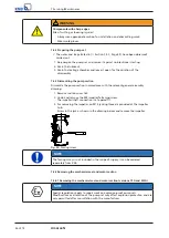
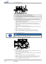
Remove the suction cover.
9.
Measure the height of screws 904 up to suction cover 162 and add 0.8 +/- 0.1
mm to the height of every screw.
10.
Re-insert the suction cover and fasten it with screws 914.03.
11.
Suspend the pump set from the hoisting tackle and rotate the impeller by hand
to check that it rotates easily.
12.
Remove the eyebolt (not included in KSB's scope of supply).
13.
Insert and tighten the impeller screw.
7.5.3 Reassambling the motor section
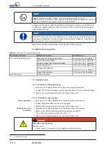
NOTE
Before reassembling the motor section, check that all joints relevant to explosion
protection (flamepaths) are undamaged. Any components with damaged
flamepaths must be replaced. Only use original spare parts made by
KSB
for
explosion-proof pumps. Observe the flamepath positions specified in the Annex.
Secure all screwed/bolted connections closing off the flameproof enclosure with a
thread-locking agent (Loctite type 243).
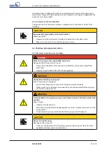
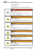
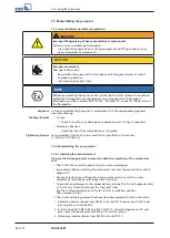
DANGER
Wrong screws/bolts
Explosion hazard!
▷
Always use the original screws/bolts for assembling an explosion-proof pump
set.
▷
Never use screws/bolts of different dimensions or of a lower property class.
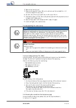
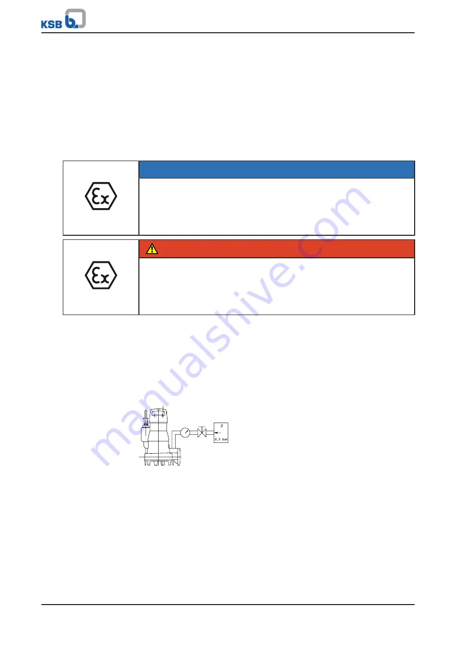
7.5.4 Leak testing (versions YLG - WLG)
After reassembly, the mechanical seal area/lubricant reservoir must be tested for
leakage. The leak test is performed using the lubricant filler opening.
Observe the following values for leak testing:
▪
Test medium:
compressed air
▪
Test pressure:
0.5 bar max.
▪
Test duration:
2 minutes
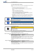
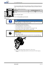
2563:115
Fig. 28:
Screwing in the testing device
1.
Unscrew and remove the screw plug and joint ring of the lubricant reservoir.
2.
Screw the testing device tightly into the lubricant filler opening.
3.
Carry out the leak test with the values specified above.
The pressure must not drop during the test period.
If the pressure does drop, check the seals and screwed connections.
Then perform another leak test.
4.
If the leak test has been successful, fill in the lubricant.
7.5.5 Checking the connection of motor/power supply
Once reassembly has been completed, carry out the steps described in
Содержание Amarex N
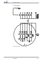
Страница 62: ...9 Related Documents 62 of 72 Amarex N 9 2 2 Version ULG Fig 33 Wiring diagram for version ULG...
Страница 70: ......
Страница 71: ......

