7 Servicing/Maintenance
46 of 72
Amarex N
WARNING
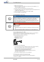
Components with sharp edges
Risk of cutting or shearing injuries!
▷
Always use appropriate caution for installation and dismantling work.
▷
Wear work gloves.
7.4.2 Preparing the pump set
ü
The notes and steps stated in
have been observed/
carried out.
1.
De-energise the pump set and secure it against unintentional start-up.
2.
Drain the lubricant.
3.
Drain the leakage chamber and leave it open for the duration of the
disassembly.
7.4.3 Dismantling the pump section
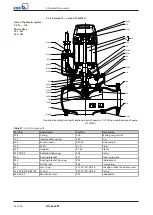
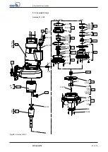
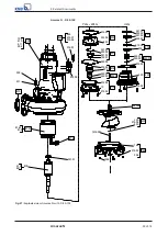
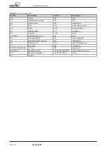
Dismantle the pump section in accordance with the relevant general assembly
drawing.
1.
Remove suction cover 162.
2.
Undo and remove the M8 impeller fastening screw.
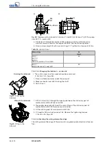
The impeller/shaft connection is a tapered fit.
3.
For removing the impeller, an M10 jacking thread is provided at the impeller
hub.
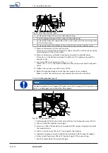
Screw in the jack as shown in the drawing below and remove the impeller.
Fig. 23:
Forcing screw
NOTE
The forcing screw is not included in the scope of supply. It can be ordered
separately from KSB.
7.4.4 Removing the mechanical seal and motor section
7.4.4.1 Removing the mechanical seal and motor section (versions YLG and WLG)
NOTE
Special regulations apply to repair work on explosion-proof pump sets.
Modifications or alteration of the pump set may affect explosion protection and are
only permitted after consultation with the manufacturer.
Содержание Amarex N
Страница 62: ...9 Related Documents 62 of 72 Amarex N 9 2 2 Version ULG Fig 33 Wiring diagram for version ULG...
Страница 70: ......
Страница 71: ......


