7 Servicing/Maintenance
49 of 72
Amarex N
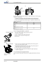
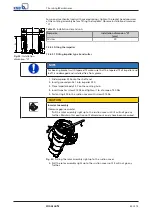
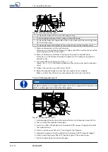
For special mechanical seals with covered springs, tighten the socket head cap screw
at the rotating assembly before fitting the impeller. Observe installation dimension
"A".
A
Fig. 24:
Installation
dimension "A"
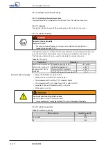
Table 21:
Installation dimension A
Pump size
Installation dimension "A"
[mm]
All sizes
29
7.5.2.2 Fitting the impeller
7.5.2.2.1 Fitting impeller type S and cutter
NOTE
For bearing brackets with tapered fit make sure that the tapered fit of impeller and
shaft is undamaged and installed free from grease.
1.
Slide impeller 230 onto the shaft end.
2.
Insert grooved pin 561 into impeller 230.
3.
Place impeller body 23-7 on the centring hub.
4.
Insert impeller screw 914.04 and tighten it to a torque of 30 Nm.
5.
Fasten ring 500 in the suction cover with screws 914.06.
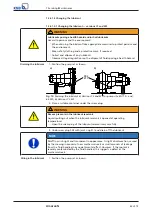
CAUTION
Incorrect assembly
Clearance gap inaccurate!
▷
Pull the rotor assembly right up to the suction cover until it will not go any
further. Maintain this position until dimensions x and y have been measured.
Fig. 25:
Pulling the rotor assembly right up to the suction cover
6.
Pull the rotor assembly right up to the suction cover until it will not go any
further.
Содержание Amarex N
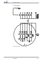
Страница 62: ...9 Related Documents 62 of 72 Amarex N 9 2 2 Version ULG Fig 33 Wiring diagram for version ULG...
Страница 70: ......
Страница 71: ......

