5 Installation at Site
28 of 72
Amarex N
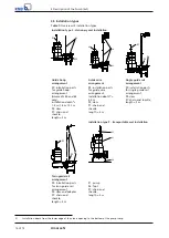
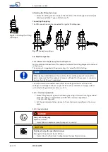
Attaching the lifting chain/rope
UG1274785
Fig. 15:
Attaching the lifting
chain/rope
1.
Attach the lifting chain or rope to the shackle on the discharge nozzle side (see
drawing and table "Types of attachment").
Connecting the piping
The DIN connection can be connected to rigid or flexible pipes.
Fig. 16:
Connection options
5.4 Electrical system
5.4.1 Information for planning the control system
For the electrical connection of the pump set observe the wiring diagrams contained
in the Annex.
The pump set is supplied with power cables; it is wired for DOL starting.
NOTE
When laying a cable between the control system and the pump set's connection
point, make sure that the number of cores is sufficient for the sensors. A minimum
cross-section of 1.5 mm² is required.
The motors can be connected to electrical low voltage networks with nominal
voltages and voltage tolerances as per IEC 38 or other networks or supply systems
with rated voltage tolerances of max. ±10 %.
5.4.1.1 Overload protection
1.
Protect the pump set against overloading by using a thermal time-lag overload
protection device in accordance with IEC 947 and local regulations.
2.
Set the overload protection device to the rated current specified on the name
plate.
5.4.1.2 Level control
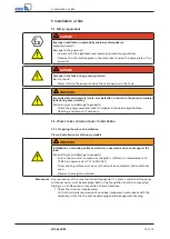
DANGER
Pump set running dry
Explosion hazard!
▷
Never allow an explosion-proof pump set to run dry!
CAUTION
Fluid level below the specified minimum
Damage to the pump set by cavitation!
▷
Never allow the fluid level to drop below the specified minimum.
Содержание Amarex N
Страница 62: ...9 Related Documents 62 of 72 Amarex N 9 2 2 Version ULG Fig 33 Wiring diagram for version ULG...
Страница 70: ......
Страница 71: ......

