Operation
45
Pos : 19.4 /Übersc hrift en/Übersc hrift en 2/ F-J/F unktion der Sc hal ter Bedi eneinheit @ 35\mod_1257922602863_78.doc @ 333387
8.1
Function of the switches on the control unit
Pos : 19.5 /BA/ Bedi enung /Eas yC ut /Funkti on der Sc halt er Bedieneinhei t mit QFB EC 7540/ 9140 @ 11\ mod_1223446903803_78.doc @ 146462
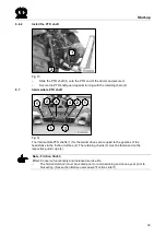
1
4
2
3
EC800038
Fig. 18:
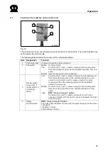
The control unit can be used to select various functions of the machine. The actual functions are
performed by the control units.
The following table explains the function of the individual switches.
Item
Designation
Function
1
Pilot lamp (red)
Lit when the control unit is turned on.
2
Flip switch
Middle: Control unit off
Top:
Control unit (1) (red 1): raises or lowers both mowing units
from the transport position to the headland position and vice-
versa.
Bottom: lower rocker switch (3) is activated.
3
Rocker switch
(only active if
rocker switch 2
is pointing
down)
Left:
Control unit (1) (red 1): raises or lowers the left mowing unit
from the working position to the headland position or vice-
versa Control unit (2) (red 2): raises or lowers the right
mowing unit from the working position to the headland
position or vice-versa
Middle: Control unit (1) (red 1): raises or lowers both mowing units
from the working position to the headland position or vice-
versa
right:
With "cross conveyor" option
Control unit (1) (red 1): raises and lowers the left cross
conveyor. Control unit (2) (red 2): raises and lowers the right
cross conveyor.
4
Rotary
potentiometer
With "cross conveyor" option
The rotary potentiometer can be used to adjust the speed of the cross
conveyors.
clockwise = faster
anticlockwise = slower
Pos : 19.6 /BA/-----Seit enumbruch------ @ 0\ mod_1196175311226_0. doc @ 4165

