background image

6

 OPERATION 

54 

SMARTMAC 400

www.krohne.com

07/2022 - 4008875401 - MA SMARTMAC_400 R01 en

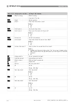
B5.4.1

Measurand

Measurand settings (only displayed if SMARTPAT COND sensor is 

connected)

B5.4.1.2

Set measurand

Setting of the measurand (only displayed if SMARTPAT COND sensor is 

connected)

Options: 

Conductivity

Resistivity

B5.4.2

Meas. range

Measuring range settings

B5.4.2.2

Lower range value

Set lower range value

Range: 0.0000…14.000 pH (only displayed if SMARTPAT PH sensor is 

connected)
Range: 100.000

-3

…20.000 µS/cm (only displayed if SMARTPAT COND sensor 

is connected) 

Range: -1500.0…+1500.0 mV (only displayed if SMARTPAT ORP sensor is 

connected)

B5.4.2.3

Upper range value

Set upper range value

Range: 0.0000…14.000 pH (only displayed if SMARTPAT PH sensor is 

connected)
Range: 100.000

-3

…20.000 µS/cm (only displayed if SMARTPAT COND sensor 

is connected) 

Range: -1500.0…+1500.0 mV (only displayed if SMARTPAT ORP sensor is 

connected)

B5.4.3

Time constant

Time constant settings

B5.4.3.2

Set time constant

Set time constant

Range: 01…60 seconds

B5.5

I/O HART

I/O HART settings

B5.5.1

Message

Message setting

B5.5.1.2

Set message

Set message (max. 32 digits)

B5.5.2

Polling address

Polling address setting

B5.5.2.2

Set polling address

Set polling address

Range: 00…63 

B5.5.3

Loop curent mode

Loop curent mode setting

B5.5.3.2

Enable current out.?

Do you want to enable the current output?

Options: 

Yes

No

B5.5.4

Device variables

Device variables are displayed (only displayed if SMARTPAT PH sensor is 

connected)

B5.5.4.1

pH value

pH value is displayed (only displayed if SMARTPAT PH sensor is connected)

-Min…Max

B5.5.4.2

Max. pH

Max. pH value is displayed (only displayed if PH sensor is connected)

B5.5.4.3

Min. pH

Min. pH value is displayed (only displayed if SMARTPAT PH sensor is 

connected)

B5.5.4.4

Electrode voltage

Electrode voltage is displayed (only displayed if SMARTPAT PH sensor is 

connected)

-Min…Max

Menu level Designation / function

Settings / descriptions

Содержание SMARTMAC 400

Страница 1: ...ration unit for digital SMARTPAT sensors SMARTMAC 400 Handbook KROHNE 07 2022 4008875401 MA SMARTMAC_400 R01 en The documentation is only complete when used in combination with the relevant documentation for the sensor ...

Страница 2: ...or any part thereof without the prior written authorisation of KROHNE Messtechnik GmbH Subject to change without notice 2 www krohne com 07 2022 4008875401 MA SMARTMAC_400 R01 en Copyright 2022 by KROHNE Messtechnik GmbH Ludwig Krohne Str 5 47058 Duisburg Germany IMPRINT ...

Страница 3: ...ion 12 2 3 Nameplate 13 3 Installation 14 3 1 General notes on installation 14 3 2 Storage and transport 14 3 3 Point to Point connection analogue digital mode 15 3 4 Pre installation requirements 16 3 5 Opening the housing 17 3 6 Wall mounting 19 3 6 1 Plastic housing 19 3 6 2 Aluminium housing 20 4 Electrical connections 21 4 1 Safety instructions 21 4 2 Important device specific notes on electr...

Страница 4: ...Illumination setting 71 6 4 8 Overflow sign and exponential format 72 6 5 SMARTPAT sensor calibration 73 6 5 1 SMARTPAT COND sensor calibration 73 6 5 2 SMARTPAT ORP sensor calibration 74 6 5 3 SMARTPAT PH sensor calibration 75 6 6 Sensor exchange function 76 7 Service 77 7 1 Maintenance and repair 77 7 2 Spare parts availability 77 7 3 Availability of services 77 7 4 Returning the device to the m...

Страница 5: ...ull information of the EU directives and standards and the approved certifications please refer to the EU declaration on the KROHNE website Hazardous areas ATEX II 2 G Ex ia IIC T4 Gb IECEx ia IIC T4 Gb QPS Ex ia IIC T4 Gb Class I Zone 1 AEx ia IIC T4 Gb UKEX II 2 G Ex ia IIC T4 Gb Other approvals and standards NAMUR recommendation NE 6 NE 21 NE 43 NE 53 NE 107 Shock resistance IEC 60721 3 4 class...

Страница 6: ...s and outputs I Current output F P Frequency pulse output S Status output C Control input CI Current input X all inputs and outputs 4 Downwards compatible changes with new functions 5 Incompatible changes i e electronic equipment must be changed Release date Electronic revision Changes and compatibility Documentation 03 2022 ER 2 0 X_ MA SMARTMAC 400 R01 DANGER For devices used in hazardous areas ...

Страница 7: ...thor and or the manufacturer The manufacturer tries always to observe the copyrights of others and to draw on works created in house or works in the public domain The collection of personal data such as names street addresses or e mail addresses in the manufacturer s documents is always on a voluntary basis whenever possible Whenever feasible it is always possible to make use of the offerings and ...

Страница 8: ...law does not allow such limitations on implied warranties or the exclusion of limitation of certain damages you may if such law applies to you not be subject to some or all of the above disclaimer exclusions or limitations Any product purchased from the manufacturer is warranted in accordance with the relevant product documentation and our Terms and Conditions of Sale The manufacturer reserves the...

Страница 9: ...n To prevent any injury to the user or damage to the device it is essential that you read the information in this document and observe applicable national standards safety requirements and accident prevention regulations If this document is not in your native language and if you have any problems understanding the text we advise you to contact your local office for assistance The manufacturer cann...

Страница 10: ... without fail Even partial disregard of this warning can lead to serious health problems and even death There is also the risk of seriously damaging the device or parts of the operator s plant WARNING Disregarding this safety warning even if only in part poses the risk of serious health problems There is also the risk of damaging the device or parts of the operator s plant CAUTION Disregarding the...

Страница 11: ...ges or signs of rough handling Report damage to the carrier and to the local office of the manufacturer INFORMATION Do a check of the packing list to make sure that you have all the elements given in the order INFORMATION Look at the device nameplate to ensure that the device is delivered according to your order Check for the correct supply voltage printed on the nameplate Figure 2 1 Example of th...

Страница 12: ...t the application The two free programmable relays and the second current output allow process control Different customer specific measurement pages with up to 4 displayed values enable a detailed monitoring of the process By using the second current output it is possible to use the backlight and high brightness LEDs for NAMUR NE 107 status signalisation Figure 2 2 Device description 1 Display 2 O...

Страница 13: ...cturer 2 Device name 3 CE marking 4 TAG number 5 Data matrix code serial number Observe the operation and installation instruction Ingress protection China RoHS Electronic Electric device waste marking 6 Power supply data Parameter of measuring unit 7 Order code Manufacturing date Internet address of manufacturer 8 Electronic revision Serial number 9 Production order SMARTMAC 400 IP66 67 LOOP 1 Ui...

Страница 14: ...he device nameplate to ensure that the device is delivered according to your order Check for the correct supply voltage printed on the nameplate CAUTION Do not make any mechanical modifications to the device This can result in the loss of proper functionality as well as the rights under the device warranty Store and transport the device in a dry dust free environment Store and transport the device...

Страница 15: ...because only one Primary master and one Secondary master are allowed Two Primary masters or two Secondary masters will cause communication errors Default master modes are SMARTMAC 400 Secondary HART modem in PACTware Primary HART Field Communicator Secondary can t be changed in most devices Figure 3 1 Overview point to point connection 1 HART master with e g PACTwareTM FDT DTM 2 HART modem 3 HART ...

Страница 16: ...e from direct sunlight The device installed in control cabinets require adequate cooling e g by fan or heat exchanger Do not expose the device to intense vibration Use assembly materials and tools in compliance with the applicable occupational health and safety directives assembly materials and tools are not part of the scope of delivery Do not make any mechanical modifications to the device This ...

Страница 17: ...into the right hinge lock and open the device 1 Lift up the housing 2 i Now you have access to the electronic compartment and the possibility to mount the device on a wall INFORMATION Clean and grease all threads each time you open the housing Use only resin free and acid free grease Before closing the cover ensure that the housing gasket is properly fitted clean and undamaged Opening the plastic ...

Страница 18: ... 1 Loosen the 2 torx screws TX20 with a torx screwdriver 2 Lift up the housing 3 i Now you have access to the electronic compartment and the possibility to mount the device on a wall For closing the housing again use the 2 torx screws with a torque of 1 5 Nm Opening the aluminium housing Figure 3 3 Opening the aluminium housing ...

Страница 19: ...e adequate cooling e g by fan or heat exchanger Do not expose the unit to intense vibration Use assembly materials and tools in compliance with the applicable occupational health and safety directives assembly materials and tools are not part of the scope of delivery CAUTION Installation assembly start up and maintenance may only be performed by appropriately trained personnel The regional occupat...

Страница 20: ... 2 Drill the 4 holes and fasten the device securely to the wall 2 Figure 3 5 Wall mounting of the aluminium housing INFORMATION For outdoor mounting we recommend the optional weather protection cover XGSH010000 for wall and pipe mounting For more flexibility and convenient mounting we recommend wall mounting brackets XGSH010030 for aluminium housing ...

Страница 21: ...areas additional safety notes apply please refer to the Ex documentation WARNING Observe without fail the local occupational health and safety regulations Any work done on the electrical components of the measuring device may only be carried out by properly trained specialists INFORMATION Look at the device nameplate to ensure that the device is delivered according to your order Check for the corr...

Страница 22: ...ower supply has an internal resistor or C and E to use the internal resistor of this device You must not connect C and D at the same time 6 Terminals for relay 1 7 Terminals for relay 2 LOOP2 LOOP2 FUNC EARTH SENSOR SHIELD SENSOR SENSOR HART HART LOOP1 LOOP1 LOOP1 RELAY1 RELAY1 RELAY2 RELAY2 J K FE S A1 B1 A2 B2 C D E F G H I S Sens Sens R1 R1 R2 R2 U U U U 1 3 5 6 7 2 4 U2 U1 250 INFORMATION The ...

Страница 23: ...utput and or NE107 LEDs and backlight 2 Connected field device e g SMARTPAT PH 3 Power supply for loop 1 Main loop for operating the device in this case with usage of internal resistor 4 Power supply for relay 1 5 Power supply for relay 2 LOOP2 LOOP2 FUNC EARTH SENSOR SHIELD SENSOR SENSOR HART HART LOOP1 250 LOOP1 LOOP1 RELAY1 RELAY1 RELAY2 RELAY2 J K FE S A1 B1 A2 B2 C D E F G H I 1 U2 3 U1 UR1 U...

Страница 24: ...will not work If the power supply is above 30 VDC the device and field device sensor may be damaged destroyed CAUTION Do not use the integrated 250 Ohm HART resistor of the device when using an Ex isolation amplifier of third party with integrated 250 Ohm HART resistor Figure 4 3 Connecting the field device cable LOOP2 LOOP2 FUNC EARTH SENSOR SHIELD SENSOR SENSOR HART HART LOOP1 LOOP1 RELAY1 RELAY...

Страница 25: ...ly for backlight and LEDs for NAMUR NE 107 signalisation Figure 4 4 Connection of second current output LOOP2 LOOP2 FUNC EARTH SENSOR SHIELD SENSOR SENSOR HART HART LOOP1 LOOP1 RELAY1 RELAY1 RELAY2 RELAY2 J K FE S A1 B1 A2 B2 D E F G H I U2 U2 S Sens U1 U1 Sens R1 R1 R2 R2 U U U U FUNC EARTH SENSOR SHIELD SENSOR SENSOR HART HART FE S A1 B1 A2 B2 LOOP1 LOOP1 LOOP1 RELAY1 A A RELAY1 A A RELAY2 A A R...

Страница 26: ... contacts Possible conditions NO normally open or NC normally closed Connection values Maximum Voltage 30 V Maximum Load Current 75 mA up to 55 C and 50 mA above 55 C Max On resistance 10 Ohm Figure 4 5 Connecting the relay outputs LOOP2 LOOP2 FUNC EARTH SENSOR SHIELD SENSOR SENSOR HART HART LOOP1 LOOP1 RELAY1 RELAY1 RELAY2 RELAY2 J K FE S A1 B1 A2 B2 D E F G H I U2 U2 S Sens U1 U1 Sens R1 R1 R2 R...

Страница 27: ...t the cap needs to be closed for a protection of the electronics parts Figure 4 6 External HART adapter Figure 4 7 Connection of the external HART adapter 1 Open the housing 2 Remove the middle M16 cable gland and screw the HART adapter 3 Connect the HART adapter to connections A2 and B2 LOOP2 LOOP2 FUNC EARTH SENSOR SHIELD SENSOR SENSOR HART HART LOOP1 LOOP1 RELAY1 RELAY1 RELAY2 RELAY2 J K FE S A...

Страница 28: ...ction or damage of the device or measuring errors also note the following items Cables may only be connected when the power is switched off Always keep the housing of the device well closed if you do not perform any installation works The function of the housing is to protect the electronic equipment from dust and moisture Check the nameplate and assure that the power supply meets the voltage of t...

Страница 29: ...T sensors it is possible to navigate through the menu by pressing If a SMARTPAT sensor is connected and cannot be found please increase the Polling address to 0 63 see function table of A3 2 or set a user specific range A 3 4 DANGER To avoid fatal injuries as well as destruction or damage of the device assure a correct installation before switching on the power This includes The device is mechanic...

Страница 30: ...krohne com 07 2022 4008875401 MA SMARTMAC_400 R01 en When the search was successful the display shows the KROHNE product name of the SMARTPAT sensor Figure 5 2 Product name of the SMARTPAT sensor HARTdevi cef ound KROHNE SM ARTPATPH ...

Страница 31: ... of the display Return to measuring mode prompt appears whether the data should be saved Press 1 to 3 times return to menu mode data saved Return to sub menu or function data saved or Select menu Select sub menu or function Use highlighted cursor to change number unit property Esc Return to main menu data not saved Return to next sub menu or function data not saved INFORMATION Always push the keys...

Страница 32: ... level 6 2 1 Menu mode structure Mainmenu Submenu A Setup A1 Language A3 HART settings A3 1 HART Master A3 2 Polling address range A3 3 User specific address A3 4 User specific range A3 5 Manual hold A3 6 Field device scan A4 Display A4 1 1 Measurement page A4 2 2 Measurement page A4 3 3 Measurement page A4 4 Trend graph A4 5 Number format A4 6 Illumination settings A4 8 Contrast A5 I O A5 2 Loop ...

Страница 33: ...4 2 Two pt calib logbook PH B4 3 One pt calib logbook PH B4 4 Error logbook B5 Setup B5 1 Manual hold B5 2 Process input B5 3 TAG B5 4 I O B5 5 I O HART B5 6 Information B5 7 Commissioning B6 Service B6 1 Trimming B6 2 Reset B6 3 Factory reset B6 4 Sensor lock B7 Replace sensor B7 1 Load from sensor B7 2 Write to sensor E Test E 1 System E1 1 PV E1 2 SV E1 3 TV E1 4 QV E2 Loop 2 E2 1 Current value...

Страница 34: ...us message always the name of the relevant status group and the status symbol is displayed Symbol Status signal Description and consequence Failure No measurement possible Function check A test function or the manual hold function is active The displayed or transferred measured value does not correspond to the actual measured value Out of specification Device is being operated out of specification...

Страница 35: ... device and replace it if necessary Current mon deviation high Current monitoring max deviation time span reached Check field device and replace it if necessary Failure Configuration USP 645 Temp wrong unit Process input for temperature has wrong unit code Change configuration of tertiary variable USP 645 Cond wrong unit Process input for conductivity has wrong unit code Change configuration of pr...

Страница 36: ...t min Resistance Min resistivity Check SMARTPAT sensor Configuration Loop current saturated The HART device reports loop current saturated 2nd status byte Check SMARTPAT sensor configuration of 4 and 20 mA values Out of specification Process L2 under saturation The measurement value is out of range The current is limited by the lower limit of the current output Check SMARTMAC 400 Loop 2 configurat...

Страница 37: ...calibration If error message appears again replace the field device Information L2 not powered This info message indicated that the second loop L2 is enabled but not powered Power Loop 2 or switch off Loop 2 HART 5 3 1 4 20 mA 5 3 2 HART com disabled HART communication disabled info Check HART communication Current monitoring active Current monitoring activated Table 6 3 Status messages and diagno...

Страница 38: ...lected in A 3 2 Range 000 063 A3 5 Manual hold Manual hold of current outputs and or relays to avoid an alarm A3 5 2 Manual hold Activate manual hold to avoid an alarm Options Yes No When message FD Field Device in multidrop mode is displayed set Polling address B5 5 2 to zero A3 5 4 1 Hold second loop Activate manual hold for second loop only displayed if second loop is activated in A5 3 1 Option...

Страница 39: ...ation of 3 measurement page A4 3 1 Displayed variables Selection of number of displayed values Options One Two Three Four A4 3 2 Value line one Selection of first displayed measuring value Options PV SV TV QV 4 20 mA L1 4 20 mA L2 A4 3 3 Value line two Selection of second displayed measuring value Options PV SV TV QV 4 20 mA L1 4 20 mA L2 A4 3 4 Value line three Selection of third measuring value ...

Страница 40: ...5 Lower range value Definition of lower range value only displayed if Manual is selected in A4 4 3 A4 4 7 Upper range value Definition of upper range value only displayed if Manual is selected in A4 4 3 A4 4 9 Show lim line relay 1 Display of limit line for relay 1 Options Yes No A4 4 11 Show lim line relay 2 Display of limit line for relay 2 Options Yes No A4 4 15 Timespan Timespan Options 15min ...

Страница 41: ...or TV Range 002 006 A4 5 6 Decimals TV Settings of decimals for TV Options Automatic N XXXX N XXX N XX N X A4 5 7 Digits QV Settings of digits for QV Range 002 006 A4 5 8 Decimals QV Settings of decimals for QV Options Automatic N XXXX N XXX N XX N X A4 5 9 Digits 4 20 mA L1 Settings of digits for 4 20 mA L1 Range 002 006 A4 5 10 Decimals 4 20 mA L1 Settings of decimals for 4 20 mA L1 Options Auto...

Страница 42: ...f A4 8 Contrast Contrast of display Range 10 10 A5 I O Settings of Loops and Relays A5 2 Loop 1 Settings for Loop 1 A5 2 1 Loop current settings Configuration of the field device s 4 20 mA Signal by HART A5 2 1 2 Lower range value Configuration of the field device s 4 mA Signal by HART Range 10 000 3 500 00 µS cm A5 2 1 3 Upper range value Configuration of the field device s 20 mA Signal by HART R...

Страница 43: ...Error function This function describes if a lower 3 5 mA or an upper 21 5 mA error value is displayed only displayed if Current Output is selected in A5 3 1 Options Hold value High error current Low error current A5 3 9 Low error current Low error current only displayed if Current Output is selected in A5 3 1 and Low error current is selected in A5 3 8 Range 3 5000 3 6000 mA A5 3 10 High error cur...

Страница 44: ...st Settings of the lower hysteresis value only displayed if Limit switch band is selected in A5 4 1 Range 0 0000 Max mA A5 4 11 Set High Alarm Settings of the upper switching threshold only displayed if Limit switch band is selected in A5 4 1 Range 0 0000 Max mA A5 4 13 Set high alarm hyst Settings of the upper hysteresis value only displayed if Limit switch band is selected in A5 4 1 Range 0 0000...

Страница 45: ... 4 1 Range 0 0000 10000 seconds A5 4 28 Cleaning lead time Setting of the delay time before cleaning starts current outputs and second relay are held only displayed if Cleaning mode is selected in A5 4 1 Range 0 0000 10000 seconds A5 4 29 Cleaning duration Setting for the cleaning duration only displayed if Cleaning mode is selected in A5 4 1 Range 0 0000 10000 seconds A5 4 30 Cleaning recov time ...

Страница 46: ...ayed if Limit switch band is selected in A5 5 1 Min Max A5 5 9 Set low alarm hyst Settings of the lower hysteresis value only displayed if Limit switch band is selected in A5 5 1 Min Max A5 5 11 Set high alarm Settings of the upper switching threshold only displayed if Limit switch band is selected in A5 5 1 Min Max A5 5 13 Set high alarm hyst Settings of the upper hysteresis value only displayed ...

Страница 47: ... 1 2 V number Order code of the device A6 1 1 3 CG number Number of CG A6 1 1 4 Device name Device name A6 1 1 5 Electronic revision Electronic Revision A6 1 1 6 Software version Software version A6 1 1 7 Display brd serialnum Display board serial number A6 1 1 8 Basic brd serialnum Basic board serial number A6 1 1 9 Electronic serialnum Electronic serial number A6 1 1 10 Production date Productio...

Страница 48: ...onnected and if Product calibration is selected in B1 1 2 1 B1 1 4 4 Save value Do you want to save the calibration value only displayed if SMARTPAT COND sensor is connected and if Product calibration is selected in B1 1 2 1 Options Yes No B1 1 4 5 All outputs on hold Primary value is displayed only displayed if SMARTPAT COND sensor is connected if Product calibration is selected in B1 1 2 1 and N...

Страница 49: ...2 1 Range 0 0000 Max B1 1 7 Calibration parameter Calibration parameters are displayed only displayed if SMARTPAT COND sensor is connected Old cell constant New cell constant Message B1 1 8 1 Save parameter Do you want to save the calibration parameter only displayed if SMARTPAT COND sensor is connected Options Yes No B1 1 8 2 Set calibration date Settting of the calibration date only displayed if...

Страница 50: ...eter Calibration parameters are displayed only displayed if SMARTPAT PH sensor is connected Slope Offset Message B2 1 7 1 Save parameter Do you want to save parameters only displayed if SMARTPAT PH sensor is connected Options Yes No B2 1 7 2 Set calibration date Setting of the calibration date only displayed if SMARTPAT PH sensor is connected and Yes is selected in B2 1 7 1 YYYY MM DD B2 1 8 All o...

Страница 51: ...es No B4 Logbooks Logbooks B4 1 Calib logbook Calibration logbook only displayed if SMARTPAT ORP sensor is connected B4 1 2 Calib logbook Calibration logbook pages with entries are displayed only displayed if SMARTPAT ORP sensor is connected ORP solution Offset Date YYYY MM DD B4 2 Two pt calib logbook Two point calibration logbook only displayed if SMARTPAT PH sensor is connected B4 2 2 Two pt ca...

Страница 52: ... B5 2 2 3 Set date Set date YYYY MM_DD B5 2 3 Temperature comp Temperature compensation only displayed if SMARTPAT PH sensor is connected B5 2 3 2 Set temp comp Setting for temperature compensation only displayed if SMARTPAT PH sensor is connected Options Automatic Manual B5 2 3 3 Manual temp comp Setting of manual compensation temperature only displayed if SMARTPAT PH sensor is connected and Manu...

Страница 53: ...e temp Set reference temperature only displayed if SMARTPAT COND sensor is connected and linear is selected in B5 2 6 2 Range 005 00 140 00 B5 2 11 Maintenance int Setting of maintenance interval When the interval is expired the sensor will output an information via HART When activating the LEDs the blue LED will light up B5 2 11 2 Set maintenance int Set maintenance interval Range 000 999 d B5 2 ...

Страница 54: ...ly displayed if SMARTPAT ORP sensor is connected B5 4 3 Time constant Time constant settings B5 4 3 2 Set time constant Set time constant Range 01 60 seconds B5 5 I O HART I O HART settings B5 5 1 Message Message setting B5 5 1 2 Set message Set message max 32 digits B5 5 2 Polling address Polling address setting B5 5 2 2 Set polling address Set polling address Range 00 63 B5 5 3 Loop curent mode ...

Страница 55: ...layed if SMARTPAT ORP sensor is connected B5 5 5 7 Min temperature Min temperature is displayed only displayed if ORP sensor is connected B5 5 6 Device variables Setting and display of device variables only displayed if SMARTPAT COND sensor is connected B5 5 6 1 PV cond resist Set PV cond resist only displayed if SMARTPAT COND sensor is connected Min Max B5 5 6 2 Max PV Max PV is displayed only di...

Страница 56: ... solution 2 pH value of buffer solution 2 is displayed only displayed if SMARTPAT PH sensor is connected B5 6 2 10 Calibration method Calibration method selected in B1 1 2 1 is displayed only displayed if SMARTPAT COND sensor is connected B5 6 2 11 Cell constant Cell constant is displayed only displayed if SMARTPAT COND sensor is connected B5 6 2 12 Calibration solution Calibration solution is dis...

Страница 57: ... only displayed if SMARTPAT COND sensor is connected B5 6 5 1 Commissioning date Commissioning date is displayed only displayed if SMARTPAT COND sensor is connected YYYY MM DD B5 6 5 2 Operating hours Operating hours are displayed only displayed if SMARTPAT COND sensor is connected B5 6 5 3 Op t max OP temp Operating time max operating temperature is displayed only displayed if SMARTPAT COND senso...

Страница 58: ...nfirm lock sensor Do you confirm irreversible lock of the sensor Options Yes Warning If you select and confirm Yes the sensor is locked and the HART communication is not possible anymore The setting is not reversible anymore No B7 Replace sensor Sensor replacement support B7 1 Load from sensor Load settings from sensor B7 2 Write to sensor Write settings to new sensor E Test Device tests E1 System...

Страница 59: ... 3 Start simulation Start simulation Options Yes No E1 4 QV Set QV Range Min Max E1 4 Start simulation Start simulation Options Yes No E2 Loop 2 Test of Loop 2 only displayed if Loop 2 is activated in A5 3 1 E2 1 Current value Set current value Range 0 0000 Max E2 1 Start simulation Start simulation Options Yes No E3 Relays Test relays E3 1 Relay 1 Set relay 1 Range 1 0000 1 0000 E3 1 Start simula...

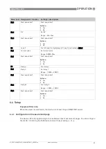
Страница 60: ... variables please look into the manual of the connected field device This 2 measurement page shows two values with the corresponding unit 1 Measurement page Figure 6 1 1 Measurement page 1 TAG 2 Measuring unit 3 Relay 2 status 4 Relay 1 status 5 Measuring value 2 Measurement page Figure 6 2 2 Measurement page 1 TAG 2 Measuring unit first value 3 Measuring unit second value 4 Relay 2 status 5 Relay...

Страница 61: ...s up to four values with the corresponding unit The number of values is freely configurable The status of the relays is displayed on the right side in this case Go to menu option A4 3 to choose between the parameters PV SV TV QV 4 20 mA L1 and 4 20 mA L2 for each value 3 Measurement page Figure 6 3 3 Measurement page 1 TAG 2 Relay 1 status 3 Relay 2 status 4 4 Measuring value 5 3 Measuring value 6...

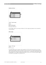
Страница 62: ... You can choose between the variables PV SV TV QV 4 20 mA L1 and 4 20 mA L2 Set the range where you can decide between manual and automatic In manual mode you can define the lower range and the upper range value Decide wether the limit lines of relay 1 and relay 2 should be displayed Trend graph Figure 6 4 Trend graph 1 TAG 2 Limit line for example relay 1 3 Trend graph 4 Limit line for example re...

Страница 63: ...e Furthermore there is a status message explaining the error category in front of each group of messages Press to get detailed information about the displayed error and leave that page by pressing Press or to leave the status page to the measurement pages for entering the menu Graph summary Figure 6 5 Graph summary 1 TAG 2 Span 3 Max measured value 4 Min measured value 5 Average measured value Sta...

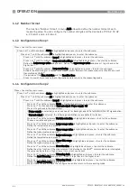
Страница 64: ...ress to enter the submenu Press or until the submenu Mode is highlighted and press to enter the submenu Press or to choose between Current output Power supply Off Press to get back in the higher level If Power supply is selected you can use Loop 2 for backlight and LEDs for NAMUR NE 107 signalisation If Current output is selected the following possibilities are available for selection Press or unt...

Страница 65: ...eds or falls below this range the relay switches You can choose if the relay opens not inverted or closes inverted when the value exceeds or falls below the band In addition two hysteresis are configurable For the upper limit you define an upper hysteresis and for the lower limit a lower hysteresis Figure 6 7 Limit switch band 1 High alarm 2 High hysteresis 3 Low hysteresis 4 Low alarm 5 Relay clo...

Страница 66: ... Decide wether the relay opens inverted or closes not inverted when the value exceeds or falls below the threshold The hysteresis is freely configurable Define an upper hysteresis if you have an upper threshold and a lower hysteresis if you have a lower threshold Figure 6 8 Limit switch threshold underrun direction 1 Hysteresis 2 Threshold 3 Relay closed not inverted 4 Relay open not inverted 5 Re...

Страница 67: ...stem alarm Loop 1 error current USP 645 and Field device status Limit switch threshold In Limit Switch Threshold mode you define a threshold When the measuring value exceeds or falls below this threshold the relay switches Figure 6 9 Limit switch threshold overrun direction 1 Threshold 2 Hysteresis 3 Relay closed not inverted 4 Relay open not inverted 5 Relay closed inverted 6 Relay open inverted ...

Страница 68: ... characteristic is highlighted and press to enter the submenu Choose between Overrun and Underrun and press Press several times to save the configuration and to return to the measuring mode Press to enter the main menu Press or until the submenu Setup is highlighted and press to enter the submenu Press or until the submenu I O is highlighted and press to enter the submenu Press or until the submen...

Страница 69: ... and press to enter the submenu Press or until the submenu Mode is highlighted and press to enter the submenu Press or until the submenu Loop 1 error current is highlighted and press Press or until the submenu Invert is highlighted and press to enter the submenu Choose between Yes and No when an inversion is required or not and press Press or until the submenu Loop 1 error current is highlighted a...

Страница 70: ...il the submenu Mode is highlighted and press to enter the submenu Press or until the submenu Field device status is highlighted and press Press or until the submenu Invert is highlighted and press to enter the submenu Choose between Yes and No when an inversion is required or not and press Press or until the submenu Field device status is highlighted and press to enter the submenu Choose between M...

Страница 71: ...ss or until the submenu Cleaning recov time is highlighted and press to enter the submenu Set sensor recovery time after cleaning with selecting position and or selecting number Press for confirmation of adjusted value Press or until the submenu Hold outp when act is highlighted and press to enter the submenu Choose between Yes and No when output should be hold or not during cleaning cycle and pre...

Страница 72: ...r display line should consist of a fixed number of digits in menu A4 5 For this purpose the corresponding function must not have the setting automatic If the measuring result in this line exceeds this number the display shows the overflow sign right beside the plus minus sign It appears as a triangle pointing to the left as shown in the following drawings Exponential format If the format of the re...

Страница 73: ...enu Press to enter the submenu Calibration Press to enter the submenu Start calibration Choose calibration method Product calibration and press Choose between Yes and No to set all outputs on hold or not and press Press when measured value is stable Press to confirm displayed calibration value Choose Yes to save value and press to go on with the calibration or choose No to abort calibration Choose...

Страница 74: ...t all outputs on hold or not and press Press to enter the submenu Start calibration Choose calibration method Input cell constant and press Choose between Yes and No to set all outputs on hold or not and press Set new cell constant with selecting position and or selecting number Press for confirmation of adjusted constant Press to confirm displayed calibration parameter Choose Yes to save paramete...

Страница 75: ...t temperature compensation value with selecting position and or selecting number Press for confirmation of adjusted value Put SMARTPAT PH sensor into buffer solution 1 and press to confirm stable value Set value of buffer solution 1 with selecting position and or selecting number Press for confirmation of adjusted value Put SMARTPAT PH sensor into buffer solution 2 and press to confirm stable valu...

Страница 76: ...sor is highlighted and press to enter the submenu Press or until the submenu Write to sensor is highlighted and press to enter the submenu After writing the settings to the new sensor the message Sensor restore complete is displayed INFORMATION When Write to sensor is started without having made a backup or a different sensor type is connected e g PH sensor instead of COND sensor the message No va...

Страница 77: ...se of a malfunction only the technical service is allowed to repair the device Never try to repair the device on your own otherwise it may come to fatal injuries destruction or damage of the device or measuring errors INFORMATION For more precise information please contact your local sales office WARNING Should you nevertheless need to return a device for inspection or repair please pay strict att...

Страница 78: ...such substances We have flushed out and neutralized all cavities in the device We hereby confirm that there is no risk to persons or the environment caused by any residual media contained in this device when it is returned Date Signature Stamp LEGAL NOTICE Disposal must be carried out in accordance with legislation applicable in your country Separate collection of WEEE Waste Electrical and Electro...

Страница 79: ...ly describes the instructions of handling and disassembling the device when it has reached the end of its useful life EOL or is disposed of after usage The information given is sufficient to gather the most important parts of the device by the end user which can be used for recycling Figure 7 1 Overview disassembly aluminium housing ...

Страница 80: ...t g lb 1 Housing PC 197 0 43 Aluminium 645 1 42 2 Cable glands PA6 V 2 CR NBR 31 0 07 PA6 V 2 CR NBR 31 0 07 3 LCD screen size 23 cm2 diverse 11 0 02 diverse 11 0 02 4 Cable PVC Copper 11 0 02 PVC Copper 14 0 03 5 PCB display size 76 cm2 FR4 57 0 13 FR4 57 0 13 6 PCB display cover size 77 cm2 FR4 23 0 05 FR4 25 0 05 7 PCB basic size 82 cm2 FR4 52 0 12 FR4 52 0 12 8 PCB basic cover size 81 cm2 FR4 ...

Страница 81: ...d can be shipped separately for reuse and or recycling INFORMATION The percentage of hazardous substances present in the components complies with RoHS INFORMATION The product does not contain harmful gases or substances There are no special guidance or actions necessary to disassemble the device CAUTION Before disassembling the device make sure you have the proper tools needed For the plastic vers...

Страница 82: ...ists of SMARTMAC 400 SMARTPAT sensor SMARTPAT VP cable Communication protocol HART 5 Display and user interface Graphic display LC display 256 x 128 pixel Operating elements 4 push buttons for operator control of the unit without opening the housing Operating menu The operation menu consists of Measuring mode 6 pages 5 measurement pages and 1 status page Menu mode variety of main and submenus that...

Страница 83: ...relay contacts are electrically isolated from each other and from all other circuits The output stages of the status outputs limit switches behave like relay contacts Possible conditions NO normally open or NC normally closed Connection values Maximum voltage 30 V Maximum load current 75 mA up to 55 C and 50 mA above 55 C Max on resistance 10 Ohm Approvals and certifications CE The device meets th...

Страница 84: ... Dimensions Plastic housing Figure 8 1 Dimensions plastic housing Dimensions mm Weight g a b c d Wall mounted 80 151 60 105 413 Table 8 1 Dimensions plastic housing in mm Dimensions inch Weight pound a b c d Wall mounted 3 15 5 94 2 36 4 13 0 91 Table 8 2 Dimensions plastic housing in inch a g ...

Страница 85: ...en Aluminium housing Figure 8 2 Dimensions aluminium housing Dimensions mm Weight g a b c d Wall mounted 86 159 60 111 855 Table 8 3 Dimensions aluminium housing in mm Dimensions inch Weight pound a b c d Wall mounted 3 39 6 26 2 36 4 37 1 89 Table 8 4 Dimensions aluminium housing in inch ...

Страница 86: ...9 NOTES 86 SMARTMAC 400 www krohne com 07 2022 4008875401 MA SMARTMAC_400 R01 en ...

Страница 87: ...NOTES 9 87 SMARTMAC 400 www krohne com 07 2022 4008875401 MA SMARTMAC_400 R01 en ...

Страница 88: ...ing solutions Engineering commissioning calibration maintenance and training services Head Office KROHNE Messtechnik GmbH Ludwig Krohne Str 5 47058 Duisburg Germany Tel 49 203 301 0 Fax 49 203 301 10389 info krohne de KROHNE 07 2022 4008875401 MA SMARTMAC_400 R01 en Subject to change without notice The current list of all KROHNE contacts and addresses can be found at www krohne com ...

Отзывы: