


8
TECHNICAL DATA
64
H250
www.krohne.com
04/2009 - 4000269302 MA H250-R02
Technical data
8.1 Operating principle
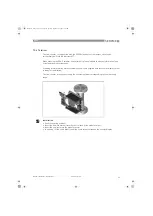
The flowmeter H250 operates on the float measuring principle. The measuring unit consists of a
metal cone in which a float can move freely up and down. The medium flows through the
flowmeter from bottom to top. The float adjusts itself so that the buoyancy force B
B
B
B, acting on it,
the form drag D
D
D
D and its weight W
W
W
W are in equilibrium: W = B + D.
W = B + D.
W = B + D.
W = B + D.
For indicators M9 and M8MG
1
the flow-dependent height of the float in the measuring unit is
transmitted by means of a magnetic coupling and displayed on a scale. For indicators M10 and
M8EG
2
the flow-dependent height of the float in the measuring unit is transmitted to the
electronic display by magnetic field sensors S1 and S2.
The flowmeters operate according to a modified float measuring principle. The guided float
adjusts itself so that the flow force acting on it is in equilibrium with the opposing spring force.
The flow-dependent position of the float in the measuring unit is displayed on a scale by means
of a magnetic coupling.
Figure 8-1: Operating principle
1
Indication principle M9 and M8MG
2
Indication principle M10 and M8EG
Operating principle of H250H and H250U
Figure 8-2: Operating principle H250H and H250U
1
H250H - horizontal flow direction
2
H250U - flow direction from top to bottom
INFORMATION!
Flowmeters H250H and H250U only work in conjunction with indicator M9.
MA_H250_R02_en_PRT.book Page 64 Tuesday, September 22, 2009 12:26 PM


