


4
ELECTRICAL CONNECTIONS
24
H250
www.krohne.com
04/2009 - 4000269302 MA H250-R02
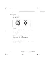
4.3 Electrical connection indicator M9
4.3.1 Indicator M9 - limit switches
The M9 indicator can be equipped with a maximum of two electronic limit switches. The limit
switch functions as a slot sensor which is operated inductively through the semicircular metal
vane belonging to the measuring pointer. The switching points are set using the contact pointers.
The position of the contact pointer is indicated on the scale.
The connecting terminals have a pluggable design and can be removed in order to connect the
cables. The built-in limit switch types are shown on the indicator.
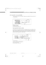
Electrical connection of the limit switches
Limit switch module
1
Min. contact
2
Max. contact
3
Locking screw
4
Maximum pointer
5
Connection terminal
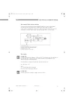
Contact
MIN
MAX
Terminal no.
1
2
3
4
5
6
Connection 2-wire NAMUR
-
+
-
+
Connection 3-wire
+
DC
-
+
DC
-
MA_H250_R02_en_PRT.book Page 24 Tuesday, September 22, 2009 12:26 PM


