


INSTALLATION
3
17
H250
www.krohne.com
04/2009 - 4000269302 MA H250-R02
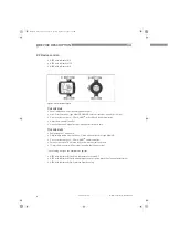
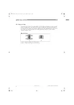
Take special note of the installation position for the H250H with horizontal flow
direction:
In order to comply with thermal parameters and measuring accuracy, H250H flowmeters for
horizontal installation are to be installed in the pipeline so that the display is located on the side
of the measuring tube. The maximum medium and ambient temperatures indicated as well as
the measuring accuracy are based on lateral installation of the display.
3.3.1 Tightening torques
For measuring devices with PTFE liner or ceramic liner and PTFE raised face, tighten the flange
threads with the following torques:
Nominal size acc. to
Bolts
Max. torque
EN 1092-1
ASME B16.5
EN
1092-1
ASME
EN 1092-1
ASME 150 lbs
DN
PN
Inches
lbs
150 lbs 300 lbs
Nm
ft*lbf
Nm
ft*lbf
15
40
½
"
150/300
4 x M 12
4 x
½
"
4 x
½
"
9.8
7.1
5.2
3.8
25
40
1"
150/300
4 x M 12
4 x
½
" 4 x 5/8"
21
15
10
7.2
50
40
2"
150/300
4 x M 16 4 x 5/8" 8 x 5/8"
57
41
41
30
80
16
3"
150/300
8 x M 16 4 x 5/8"
8 x
¾
"
47
34
70
51
100
16
4"
150/300
8 x M 16 8 x 5/8"
8 x
¾
"
67
48
50
36
MA_H250_R02_en_PRT.book Page 17 Tuesday, September 22, 2009 12:26 PM


