


ELECTRICAL CONNECTIONS
4
35
H250
www.krohne.com
04/2009 - 4000269302 MA H250-R02
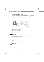
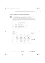
Power supply M10 with electrical isolation
The circuitry to other devices must be designed with special care. In some circumstances,
internal connections in these devices (e.g. GND with PE, ground loops) may lead to
impermissible voltage potentials, which can compromise the function of the device itself or a
connected device. In such cases a protected extra-low voltage (PELV) is recommended.
Power supply
The required supply voltage can be calculated using the formula below:
U
ext.
= R
L
.
22 mA + 16 V
where
U
ext.
= the minimum supply voltage and
R
L
= the total measuring loop resistance is.
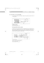
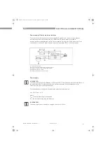
1
Terminal connection
2
Converter supply isolator with electrical isolation
3
Power supply (see supply isolator information)
4
Measuring signal 4...20 mA
5
External load, HART
®
communication
INFORMATION!
The supply voltage has to be between 16 VDC and 32 VDC. This is based on the total resistance of
the measuring loop. To determine this, add up the resistances of each component in the
measuring loop (not including the device).
INFORMATION!
The power supply has to be able to supply a minimum of 22 mA.
MA_H250_R02_en_PRT.book Page 35 Tuesday, September 22, 2009 12:26 PM


