7
•
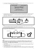
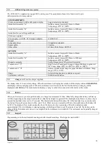
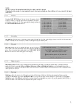
The instrument selects the appropriate guiderail using the data entered and now displays the following. The sensor set can
be “A”, ”B”, ”C” or “D” and the mode Reflex or Diagonal.
•
Take the guiderail selected by the instrument out of the case, retract the sensor blocks back into the guiderail by turning the
knurled knobs clockwise. If transducer “C” is selected and these blocks are available, remove “B” transducer set and
replace with “C” transducer set.
•
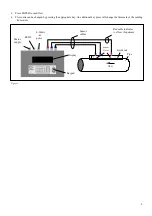
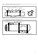
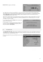
Apply couplant to both sensor blocks as shown, then attach to the pipe using the appropriate mounting hardware.
•
•
In most cases the guide rail selected will suit the application. The user can choose another rail and/or sensors to increase
sensitivity, signal strength or change flow range (see 3.4.1 – Select Sensor Set).
NOTE:
If the instrument has selected a guiderail assembly to work in DIAGONAL MODE the floating transducer has to be
removed and placed on the opposite side of the pipe, using the diagonal beam rail and the appropriate mounting
hardware (See 2.9 - ATTACHING THE TRANSDUCERS).
•
Connect the red/blue and black sensor cables to both the electronics and the guiderail assembly. The red cable indve
flow if upstream.
•
Attach to the pipe as shown in figure 3 and turning the knurled knob anti-clockwise, screw the fixed transducer to the pipe,
making finger tight contact.
•
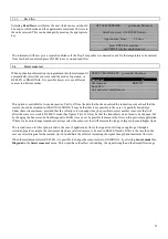
Press ENTER and the display will show the separation distance in mm.
•
Set the separation distance (see figure 3) by sliding the floating transducer along the scale until the front edge of the block is
at the recommended distance. Now turn the knurled knob anti-clockwise, until in finger tight contact with the pipe surface.
ATTACH SENSORS
yy-mm-dd hh:mm:ss
Attach sensor set X in XXXXXX mode
(RED connector UPSTREAM)
Approx. max. flow:
X.XX m/s
Press ENTER to continue
or SCROLL to select another sensor
COUPLANT
floating sensor block
fixed sensor block
Figure 2
Figure 3
Example: REFLEX MODE OPERATION
separation
distance
floating transducer
fixed transducer
straps

