45
CRIMPED CLEVIS
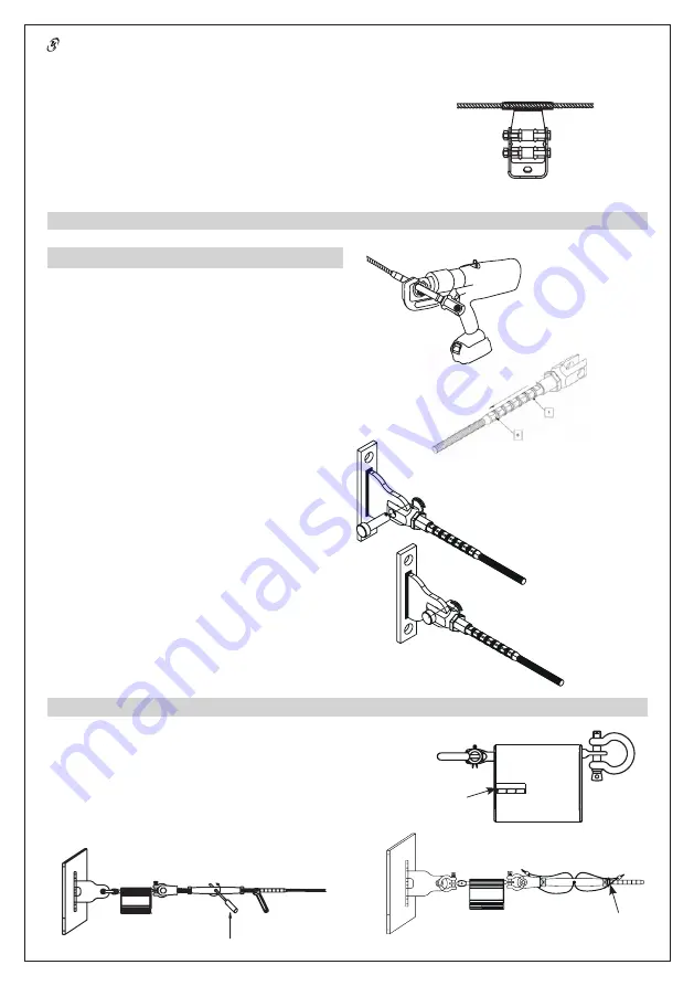
Once you have adjusted its length, introduce the cable into the FA 60 205
00 tensioner crimped clevis. At least 100 mm of cable must be fed into the
tube. Mark the cable to check the length introduced into the tube. If the
length measured is the minimum length required, reintroduce the cable into
the tube. Using the crimping tool, start crimping at point 1 by positioning
the crimper jaws in the centre of the crimp markers on the crimped clevis.
Continue crimping in the direction indicated on the drawing until you have
finished crimp No. 6. Rotate the crimping tube by 45° between crimps to
prevent it from becoming deformed over its length. Refer to the crimping
machine user instructions before commencing. When you have finished
crimping, apply coloured lacquer to the cable and tube which will act as an
indicator in case the cable slips inside the tube.
Particular care must be taken when carrying out this operation as it cannot
be reversed and it is central to the strength of the system and the safety
of its users.
FA 60 205 00
Next, pass the cable through all of the intermediate components.
The crimped clevis must be in its shortest position, i.e. fully screwed in and
locked with the nut (see the crimped clevis technical description drawing
in the technical file). Remove the pin from the clevis assembly shaft so that
it can be removed. Next, fit the crimped clevis to the end piece and put the
shaft back in position through the clevis and the end piece. Put the safety
pin back on the shaft.
INSTALLATION TENSION
Place the lifeline under tension using the FA 60 203 00 tensioner by rotating the
main tensioner body using a shaft going through the hole until the last absorber coil
touches the absorber’s tension indicator recess. The tensile force should then be of
the order of 80 to 100 daN.
When you have finished putting the system under tension, tighten up the 2 lock
nuts against the body of the tensioner to lock the assembly in place. Apply some
thread lock to the grub screws and screw them into the nuts.
Fit one anti-tamper seal
between the main tensioner body hole and its clevis and another between the main
tensioner body hole and the seal ring (see drawing opposite).
Tension indicator
Seal ring


