background image

GG-11008      Edition  1.2 


- 47 - 

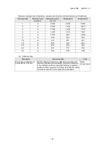
Stimulus measurement intensities, measurement points, standard values and tolerances 

Intensity [dB] 

Measurement 

positions 

Standard values 

[cd/m

2

MIN[cd/m

2

MAX[cd/m

2

2,528 

2,023 

3,034 

2,008 

1,607 

2,410 

1,595 

1,276 

1,914 

1,267 

1,014 

1,521 

1,007 

805 

1,208 

800 

640 

959 

12 

201 

161 

241 

18 

50.5 

40.4 

60.5 

20 

31.8 

25.5 

38.2 

24 

12.7 

10.1 

15.2 

30 

3.18 

2.55 

3.82 


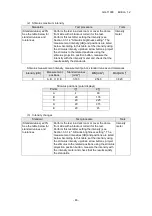
(4)  Stimulus size 

Standards 

Test procedure 

Tools 

Minor axis of stimulus at 
points B to E: 9±1mm 

Set the stimulus intensity to 0dB using the stimulus 
intensity up/down arrow buttons, project the stimulus 
to the related positions using the stimulus projection 
position button, measure the minor axis with the scale 
and check that the results satisfy the standards. 

Scale 

Visual check 


Содержание AP-7000

Страница 1: ...GG 11008 Edition 1 2 Edition 1 2 November 2012 Model Name FT10...

Страница 2: ...sity sensor 9 Replacing speaker 10 Replacing board PC 10 Replacing monitor 11 Replacing stimulus lamp 12 Replacing background LEDs 13 Replacing fuses 14 4 Error Messages and Corrective Actions 15 5 Cl...

Страница 3: ...le wrap bag and put it in the packing carton prepared in step 1 above Figure 2 3 Outer sleeve and top pad Put outer sleeve and top pad on the main unit Figure 3 4 Accessory box Put the accessory box i...

Страница 4: ...ive screws and remove the cover Be careful of 9530 connected through the harness Figure 7 2 Remove the left side cover Remove five screws and remove the cover Figure 8 3 Remove the center cover Remove...

Страница 5: ...For details see the replacement parts list Background intensity sensor Main board Background LEDs white Monitor Background LEDs yellow Stimulus intensity sensor Stimulus lamp Board PC Fuses Switching...

Страница 6: ...round LED white Background LED yellow SC36MF1_1230 FT10_1337 FT10_9580 FT10_9581 P 8 P 8 P 13 P 13 Stimulus intensity sensor Background intensity sensor Monitor Board PC FT10_9540 FT10_9610 CR121DXL19...

Страница 7: ...be sure to reconnect the cables to the right destinations see the wiring diagram Initial data processing The initial data FTflash ini is processed as shown in Figure 12 FT10 board PC When the software...

Страница 8: ...s There are two switching power supplies A and B which are mounted to the left side viewed from the chin rest of the main unit Figure 14 When replacing switching power supply A loosen three screws The...

Страница 9: ...ic shock and move the camera back and forth for focusing while viewing the monitor When focusing lift the lens frame put a finger or another object Figure 16 or paste a piece of paper written with a l...

Страница 10: ...s vertical stroke so that it is positioned in the vicinity of the center of the dome hole and fix it Then align the stimulus so that the amount of light on the acceptance surface becomes the highest l...

Страница 11: ...d remove the fixing plate Figure 22 Replacing board PC 1 Remove the board PC The board PC is positioned on the right side viewed from the monitor Loosen three screws fixing the board PC cover and remo...

Страница 12: ...Figure 25 on the rear side of the monitor unit loosen four screws and remove the monitor unit Figure 26 Remove four screws from the monitor and remove the L shaped brackets from the monitor 2 Mount t...

Страница 13: ...ulus lamp and lift the lamp unit Figure 29 3 Replace the lamp Pull out the stimulus lamp and insert a new lamp When handling the new lamp use gloves and do not directly touch the glass part of the lam...

Страница 14: ...it Figure 31 Loosen two screws remove the base loosen four screws holding the board and remove the board Figure 32 For the LED colors see Figure 33 Figure 31 Figure 32 Before replacing the lamp be sur...

Страница 15: ...e case Disconnect the power cable and using a slotted screwdriver pull the AC inlet fuse case to this side to remove it Figures 34 and 35 2 Replace the fuses Replace the fuses and put the fuse case in...

Страница 16: ...drive USB flash drive etc specified as the data save destination are surely connected and normally operating If any of those components is not correctly connected or normally operating restore the no...

Страница 17: ...being displayed If the current date and time are incorrect press Date to open the date setting dialog and then set the correct date and time Even if the current date and time are correct this message...

Страница 18: ...elete or Cancel not to delete Axis is not entered OK has been pressed with Cyl Cylindrical diopter power input and Axis Axis degree not input in the Correction value input dialog for the patient infor...

Страница 19: ...on the examination screen at the time of examination startup with the fovea examination set to ON The fixation target is automatically moved to 4 points at the lower center Press OK to start the fovea...

Страница 20: ...es Causes and corrective actions The combined data is not saved Continue operation Attempt has been made to change over the screen to another without saving the result of data combination To save the...

Страница 21: ...gure 37 Never remove parts not specified Cleaning lens in section A Pull out the lamp and remove the lens frame and mirror holder Pull out the lamp together with its holder remove the lens frame by lo...

Страница 22: ...and bond the cover with Super X etc Cleaning lenses in section B 1 Wipe five sides of lenses while sliding For lenses in section B five sides can be wiped as they are Figure 41 For wiping side 6 remov...

Страница 23: ...protection glass and mirror Wipe side 6 in section B the protection glass and the removed mirror Figure 44 After wiping remount only the mirror at the approximate original position Note If the mirror...

Страница 24: ...ors and lens Wipe the mirror from the inside of the removed mirror unit and wipe both sides of the lens Figure 46 Also wipe the internal mirror of the cylindrical unit mounted on the main unit Figure...

Страница 25: ...software see Section 6 Using Jig Software and start Rotary motor setting of Setting mode Select Open of Shutter Figure 49 and check that red light is emitted from the cylindrical unit with the mirror...

Страница 26: ...hat the red round light described in 2 is emitted to the center of it After adjustment check that the screws are tightened and secure them with locking screws 4 Reset the jig software Check the items...

Страница 27: ...thernet Ethernet I O 200W 12V 60W 12V 200W 12V 200W 12V 60W 12V 60W 12V RTC RTC 12 1inch XGA 12 1inch XGA CR121DXL1101V20 COM2 12V LVDS HK1298 TRX100BTH 100Base T HK1296 HEW4 0 HD64F36077LH HK1337 Ri2...

Страница 28: ...t in orange STANDBY and set the power switch OFF turn to side Note To protect the system from destruction never set the power switch OFF without performing steps 1 to 3 above Hardware initialization T...

Страница 29: ...nd lamps are faulty If right or left appears the related lamp is faulty Possible causes Sensor covered with head band etc Low intensity of background lamp Contamination of background lamp sensor Break...

Страница 30: ...n the room and perform this operation Cancel 2 Same as Cancel in above 2 6 2 2 Starting and Exiting Jig Software Starting 1 Set the power switch ON while pressing the response switch 2 Keep pressing t...

Страница 31: ...reen Pressing Upgrading button starts the upgrading application 6 3 2 PC setting 1 My Computer 2 Network 3 Control Panel 4 Trash box 5 Command Prompt 6 Touch Panel Pressing one of these buttons starts...

Страница 32: ...afely disconnect a hardware device 10 The driver installation Used for installing a printer driver with virus software installed It allows installing the driver after cancelling the system protection...

Страница 33: ...reen Notes 1 Pressing Save and Exit saves the current settings in the flash ROM of the main board and opens the base menu screen Press this button only when the settings are changed using Setting mode...

Страница 34: ...ness setting Infrared LED brightness setting Pressing OK returns to the jig software menu screen Pressing one of item buttons opens the setup screen for the item OK and Cancel buttons on item screens...

Страница 35: ...mulus lamp goes lit 2 Using the right and left arrow buttons to the right side of the related setup value adjust the turret of each motor so that it is positioned at the center of the light path while...

Страница 36: ...2 Using the right and left arrow buttons on the right side of the screen adjust the stimulus so that it is positioned at the dome center LED while checking visually 3 Pressing Position gap check move...

Страница 37: ...e stimulus of the size selected in the related stimulus position Pressing one of stimulus size buttons or sets the related stimulus size Using the right and left arrow buttons on the right side of the...

Страница 38: ...lamp intensity read by the sensor and Old sensor level is the current setup value 2 Using an intensity meter adjust the lamp power with the up and down arrow buttons on the right side of the screen s...

Страница 39: ...ent lamp intensity read by the sensor and Old sensor is the current setup value For Sensor level only the combinations currently ON are updated occasionally 2 Adjust the intensity with background colo...

Страница 40: ...n for adjustment 1 The screen shows the fixation LED intensity setup value at the center LED brightness is the current fixation LED intensity and Old brightness is the current setup fixation LED inten...

Страница 41: ...sity at the pupil position with Center button selected The measurement waveform is 940nm Adjust the LED intensity using the right and left arrow buttons on the right side of the screen so that the mea...

Страница 42: ...of field check 4 Stimulus background brightness check 5 Chin stand sensor check 6 Fixation LED check Pressing Exit returns to the jig software menu screen Pressing one of item buttons opens the setup...

Страница 43: ...anges the number and turret by 1 Check that pressing the right left arrow button increments decrements the number and darkens the stimulus Check that for ND2 the stimulus darkens as the number increas...

Страница 44: ...that the projected stimulus is within the allowable circle of the jig Also visually check the projected stimulus for its focus vignetting and flare 2 Press Sensor and visually check that the stimulus...

Страница 45: ...h view angle 40 or more Press sequentially buttons A to L and check that all stimuli projected to stimulus positions for A to L are visible Also visually check the projected stimulus for its focus vig...

Страница 46: ...st procedure Tools Intensity at points B to E 10 1cd m 2 white 100 10cd m 2 yellow Perform the test in a dark room or cover the dome front side with a blackout curtain for the test For details see the...

Страница 47: ...ntensity measurement points standard values and tolerances Intensity dB Measurement positions Standard values cd m 2 MIN cd m 2 MAX cd m 2 0 A B C D E 3 183 2 546 3 820 Stimulus positions polar displa...

Страница 48: ...08 6 A 800 640 959 12 A 201 161 241 18 A 50 5 40 4 60 5 20 A 31 8 25 5 38 2 24 A 12 7 10 1 15 2 30 A 3 18 2 55 3 82 4 Stimulus size Standards Test procedure Tools Minor axis of stimulus at points B to...

Страница 49: ...eft moving buttons at the center on the right side The chin rest moves when a chin rest moving button is pressed and stops when the button is released The screen shows the chin rest moving time at the...

Страница 50: ...heck that Left display turns to red Check that Right Left display turns to blue when the hand is released Visual check b Movement Standards Test procedure Tools Chin rest movement speed Lower end Uppe...

Страница 51: ...t end 31 5 to 38 5 mm Moving distance from lower end to upper end 63 to 77mm When measuring from the right end to left end 1 Using chin rest moving button Right move the chin rest to the right end 2 U...

Страница 52: ...and insertion Standards Test procedure Tools Movement and insertion shall be normal and smooth 1 Press the switch five times and check that the movement is normal and smooth 2 Connect and disconnect t...

Страница 53: ...uttons Center macula Assistance and Lower Left intensity up down buttons and intensity The fixation target type selection button being lit turns to red For the fixation target intensity display the re...

Страница 54: ...inity of the central fixation target View the central fixation target from the dome center and check that there is no unnecessary reflection in the vicinity of the central fixation target Visual check...

Страница 55: ...he currently entered serial No appears on the right side 2 Configured data preservation 3 Configured data reading 4 Configured data clear Pressing Exit returns to the jig software menu screen Pressing...

Страница 56: ...en the system menu screen and check that the correct serial No appears next to Serial number Visual check 6 4 2 Configured data preservation Save the current settings to the flash memory of the panel...

Страница 57: ...GG 11008 Edition 1 2 56 7 Wiring Diagram...

Страница 58: ......

Отзывы: