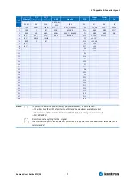
27 Appendix E: Connector Layout
Kontron User's Guide EPIC/CE
97
Ethernet
PS/2
Keyboard
PS/2
Mouse
USB
Line-In
GPIO
Power
ATX
Power
AT
Fan
Pin
X5, X21
X18
X18
X5, X20, X21,
X25
X14
X3
X7
X8
J1
1
TXD+
KBDAT
MSDAT
VCC * ***
AUXL_C/REAR_L
GP0
PS_ON
V5S *
Sense
2
TXD-
NC
NC
USB-
ASGND
GP14
GND
GND
VCC *
3
RXD+
GND
GND
USB+
AUXR_C/ REAR_R
GP1
GND
GND
GND
4
NC **
VCC *
VCC *
GND
ASGND
GP15
+12V *
VCC12 *
5
NC **
KBCLK
MSCLK
GP2
+3.3V *
6
RXD-
NC
NC
GP16
+5V_SB
7
NC **
GP3
+5V
8
NC **
GP17
+5V
9
GP4
-12V
10
GP18
GND
11
GP5
12
GP19
13
GP6
14
GP20
15
GP7
16
GP21
17
GP8
18
GP22
19
GP9
20
GP23
21
GP10
22
GP24
23
GP11
24
GP25
25
GP12
26
GND
27
GP13
28
GND
Notes
: (*)
To protect the external power lines of peripheral devices, make sure that:
-- the wires have the right diameter to withstand the maximum available current
-- the enclosure of the peripheral device fulfils the fire-protecting requirements of
-- IEC/EN 60950.
(**)
Do not connect anything to these signals.
(***) The internal USB ports 4 and 5 are not protected on the power lines. An additional resetable fuse is
recommended.
Содержание EPIC/CE
Страница 1: ...Kontron User s Guide EPIC CE Document Revision 1 14...
Страница 2: ...This page intentionally left blank...
Страница 88: ...25 Appendix C Block Diagram Kontron User s Guide EPIC CE 88 25 Appendix C Block Diagram...
Страница 90: ...26 Appendix D Mechanical Dimensions Kontron User s Guide EPIC CE 90 26 2 Connector Locations Pin 1...
Страница 93: ...27 Appendix E Connector Layout Kontron User s Guide EPIC CE 93 27 2 Bottom Side...


