13 Parallel-Port Interface
Kontron User's Guide EPIC/CE
41
13
Parallel-Port Interface
The EPIC/CE incorporates an IBM XT/AT compatible parallel port. It supports uni-directional, bi-
directional, EPP and ECP operating modes.
13.1
Connector
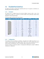
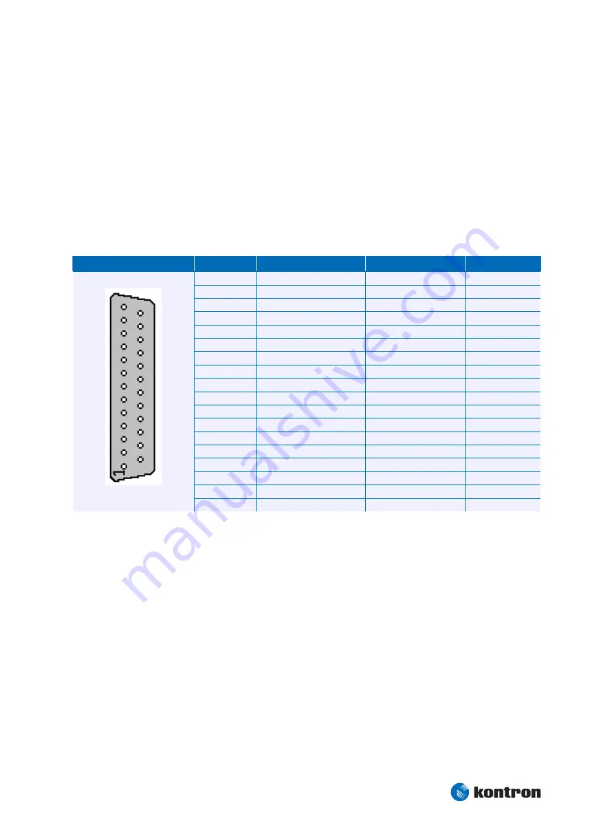
The parallel port is available through the standard DSUB25 connector which is part of the
multifunctional Connector X1 on the front. To find the location of the parallel port, please see the
Appendix E: Connector Layout chapter.
The following table shows the pin-out of the connector.
Header
Pin
Signal Name
Function
In / Out
1
/STB
Strobe
Out
2
PD0
Data 0
I/O
3
PD1
Data 1
I/O
4
PD2
Data 2
I/O
5
PD3
Data 3
I/O
6
PD4
Data 4
I/O
7
PD5
Data 5
I/O
8
PD6
Data 6
I/O
9
PD7
Data 7
I/O
10
/ACK
Acknowledge
In
11
/BUSY
Busy
In
12
PE
Paper out
In
13
/SLCT
Select out
In
14
/AFD
Autofeed
Out
15
/ERR
Error
In
16
/INIT
Init
Out
17
/SLIN
Select in
Out
18 - 25
GND
Signal Ground
--
13.2
Configuration
The parallel-port mode, I/O addresses, and IRQs are changeable from the BIOS Setup Utility. You can
program the base I/O-address 378h (default), 3BCh or 278h. You can set the parallel port mode to
disable, enable or AUTO (default). You can choose IRQ5 or IRQ7 as the parallel-port interrupt.
Refer to the I/O Device Configuration Submenu in the Appendix B: BIOS Operation chapter for additional
information on configuration.
Содержание EPIC/CE
Страница 1: ...Kontron User s Guide EPIC CE Document Revision 1 14...
Страница 2: ...This page intentionally left blank...
Страница 88: ...25 Appendix C Block Diagram Kontron User s Guide EPIC CE 88 25 Appendix C Block Diagram...
Страница 90: ...26 Appendix D Mechanical Dimensions Kontron User s Guide EPIC CE 90 26 2 Connector Locations Pin 1...
Страница 93: ...27 Appendix E Connector Layout Kontron User s Guide EPIC CE 93 27 2 Bottom Side...


