7.3 Central lubrication system
Special equipment, attachments
7-6
WA70-7 – VENAM02003
7.3.2
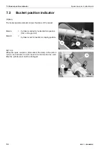
Operating the central lubrication system
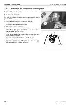
Position of the lubrication pump:
To the left on the front frame.
For more details see “Check central lubrication system, add
grease” (5-44).
1. Turn the starting switch to the 'B' (ON) position.
This switches on the lubrication pump.
2. Observe the grease container.
When the paddle agitator operates in the grease container,
the lubricating system is in order.
If the paddle agitator does not turn, then the automatic lubri-
cation does not function.
Consult your Komatsu distributor to rectify the fault.
If grease has leaked out of the pressure control valve (1),
please contact your Komatsu distributor.
1
A
B
C
G0070421
Содержание WA70-7
Страница 2: ......
Страница 3: ...Foreword WA70 7 VENAM02003 1 1 1 Foreword...
Страница 23: ...Foreword 1 5 Table of contents WA70 7 VENAM02003 1 21 Blank for technical reason...
Страница 28: ...1 7 Equipment Foreword 1 26 WA70 7 VENAM02003...
Страница 75: ...Operation WA70 7 VENAM02003 3 1 3 Operation...
Страница 114: ...3 2 Descriptions of the individual elements Operation 3 40 WA70 7 VENAM02003 Fuse allocation...
Страница 185: ...Troubleshooting WA70 7 VENAM02003 4 1 4 Troubleshooting...
Страница 203: ...Maintenance WA70 7 VENAM02003 5 1 5 Maintenance...
Страница 276: ...5 8 Maintenance procedure Maintenance every 2000 service hours Maintenance 5 74 WA70 7 VENAM02003...
Страница 277: ...Technical data WA70 7 VENAM02003 6 1 6 Technical data...
Страница 283: ...Special equipment attachments WA70 7 VENAM02003 7 1 7 Special equipment attachments...
Страница 291: ...Index WA70 7 VENAM02003 8 1 8 Index...
Страница 296: ...8 1 Index Index 8 6 WA70 7 VENAM02003...
Страница 297: ...Notes WA70 7 VENAM02003 9 1 9 Notes...
Страница 298: ...Notes 9 2 WA70 7 VENAM02003...
Страница 299: ...Notes WA70 7 VENAM02003 9 3...
Страница 300: ...Notes 9 4 WA70 7 VENAM02003...
Страница 301: ...Notes WA70 7 VENAM02003 9 5...
Страница 302: ...Notes 9 6 WA70 7 VENAM02003...


