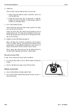
background image

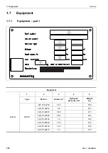
1.7  Equipment

Foreword

1-26

WA70-7 – VENAM02003

Содержание WA70-7

Страница 1: ...imes and have all personnel read it periodically Operation and Maintenance Manual VENAM02003 DANGER Komatsu has had this Operation and Maintenance Manual translated into some other languages used in t...

Страница 2: ......

Страница 3: ...Foreword WA70 7 VENAM02003 1 1 1 Foreword...

Страница 4: ...ual and the safety labels affixed to the machine thoroughly and be sure that you understand them fully Keep this manual at the storage location for the Operation and Maintenance Manual given below Hav...

Страница 5: ...ification to the machine by the owner voids the manufacturer s declaration of conformity Our continuous efforts to improve the machine s design may result in minor changes to the machine The introduct...

Страница 6: ...l lowing safety instructions are observed If you are installing electrical or electronic equipment and or components in the machine and connect them to the vehicle s electrical system you are obliged...

Страница 7: ...inform you that there is a potentially hazardous situation that may lead to personal injury or damage In this manual the following signal words are used to express the potential level of hazard DANGER...

Страница 8: ...y are not locked may result in serious injury or death Other signal words In addition to the above the following signal words are used to provide useful information or indicate precautions that should...

Страница 9: ...od of avoiding the haz ardous condition is shown inside a circle Komatsu cannot predict every circumstance that might involve a potential hazard in operation and maintenance Therefore the safety messa...

Страница 10: ...ing 1 3 1 Intended use If you use the machine for any other purpose than those speci fied above we will not accept any responsibility for its safety Any considerations regarding safety will then be up...

Страница 11: ...ts Let the engine run at idle for 5 minutes after starting Avoid operation with heavy loads or at high engine speeds Avoid sudden starts and stops hard acceleration and sud den steering movements exce...

Страница 12: ...e machine 1 4 1 Product identification number PIN Machine serial no plate and its position Position of the serial no plate 1 Serial number stamp 2 The plate is on the right side of the machine s front...

Страница 13: ...hine WA70 7 VENAM02003 1 11 1 4 2 Engine serial no plate Engine serial no plate 1 4 3 Axle serial no plate Axle serial no plate 1 Rear axle Left Front axle Right 1 4 4 Transmission serial no plate Tra...

Страница 14: ...erator s seat 1 4 6 Operator s seat serial no plate Operator s seat serial no plate Under the bellows at the front of the seat or on the rear lower frame arrow mark 1 4 7 Fluorinated greenhouse gases...

Страница 15: ...he European Machine Directive lies with the customer that commissions the retrofit of the machine In the case of tools e g load buckets retrofitted by a third party supplier the technical specificatio...

Страница 16: ...s of the following EU Directives explanation of machine category Machinery Directive 2006 42 EC Electro Magnetic Compatibility Directive 2004 108 EC until 19 April 2016 2014 30 EU after 20 April 2016...

Страница 17: ...12 1 4 6 Operator s seat serial no plate 1 12 1 4 7 Fluorinated greenhouse gases 1 12 1 4 8 Serial number and distributor 1 13 1 4 9 Retrofitting by third party suppliers 1 13 1 4 10 Declaration of C...

Страница 18: ...ilation system 3 43 3 2 13 Air conditioner 3 45 3 3 Operation 3 46 3 3 1 Checks before starting 3 46 Visual inspection 3 46 Checks before starting the engine 3 49 Adjustments before starting 3 59 3 3...

Страница 19: ...ching the work equipment 3 89 Removing the work equipment 3 92 Removing the multi purpose bucket 3 93 Bucket level indicator 3 93 3 3 13 Switching off the engine 3 94 3 3 14 Checks after switching off...

Страница 20: ...s 4 18 4 6 7 Operator s cab 4 18 5 Maintenance 5 1 5 1 Maintenance guide 5 2 5 1 1 Tipping up the operator s cab 5 3 5 1 2 Tipping down the operator s cab 5 5 5 2 Basic maintenance guidelines 5 10 5 2...

Страница 21: ...40 Lubrication articulated steering 5 40 5 8 7 Maintenance every 50 service hours 5 41 Battery check fluid level 5 41 Lubrication work equipment 5 42 Check central lubrication system add grease 5 44...

Страница 22: ...al data 6 1 6 1 Technical data 6 2 6 1 1 WA70 7 6 2 6 2 Noise emission levels 6 3 6 3 Vibration levels 6 4 6 4 Limit values for slopes 6 6 7 Special equipment attachments 7 1 7 1 E C S S 7 2 7 1 1 Des...

Страница 23: ...Foreword 1 5 Table of contents WA70 7 VENAM02003 1 21 Blank for technical reason...

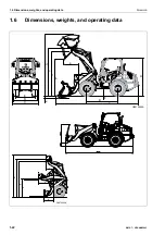
Страница 24: ...1 6 Dimensions weights and operating data Foreword 1 22 WA70 7 VENAM02003 1 6 Dimensions weights and operating data k l m n g h j G0070229A G0070228A e b d a f c F A H B E C D...

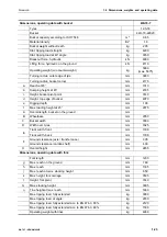
Страница 25: ...bucket mm 4070 e Digging depth mm 100 f Max loading height at 45 mm 2875 A Overall length bucket on the ground mm B Wheelbase mm 2050 C Bucket width mm 1800 D Width over tyres mm 1625 E Track width fr...

Страница 26: ...ent part 1 Equipment 1 2 3 4 5 Type Part no Volume m Hydraulic pressure bar Weight kg Bucket WA70 7 42T 70 32230 0 75 590 42U 70 32210 0 8 615 42U 70 22010 0 85 273 42U 70 22020 0 85 294 42U 70 22140...

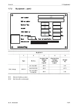
Страница 27: ...pment 1 2 3 4 5 Type Part no Payload fork carriage STD kg pair Payload fork carriage with CTW kg pair Weight kg Fork carriage WA70 7 42T 70 22051 2120 215 42U 70 22180 2120 221 5 42T 70 32300 Collapsi...

Страница 28: ...1 7 Equipment Foreword 1 26 WA70 7 VENAM02003...

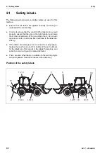
Страница 29: ...2 Safety WARNING Please read and make sure that you fully understand the precautions described in this manual and the safety labels on the machine When operating or servicing the machine always follo...

Страница 30: ...them clean at all times When you clean them do not use organic solvents or petrol as this could lead to the label dis solving If the labels are damaged lost or cannot be read properly replace them wi...

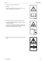
Страница 31: ...transport 2 Caution when leaving the operator s seat 09654 C0481 This symbol highlights the danger of unexpected movement of the stopped machine Lower the work equipment to the ground activate the loc...

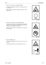
Страница 32: ...01 This symbol highlights the risk of crushing if the work equip ment falls Stay away from the raised work equipment 6 Caution explosion 09659 A057B or 09659 A0641 There is a risk of explosion that co...

Страница 33: ...k 8 Caution risk of burning from coolant 09653 A0481 This sign warns of the risk of burning posed by spraying hot water or oil if the radiator cap or the hydraulic tank lid on the hot radiator or hydr...

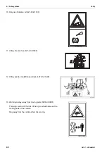
Страница 34: ...the machine 421 93 H1830 12 Lifting position mark transport lock 42T 93 21A20 13 Warning to stay away from moving parts 09162 C0881 This sign warns of the risk of being crushed between the moving par...

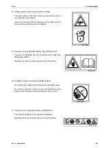
Страница 35: ...08 A1681 This symbol highlights the risk of electrocution while han dling power cables Read the manual to ensure safe and correct handling 16 Prohibition of short circuit starts 09842 A0481 Do not sta...

Страница 36: ...ng object protection systems ROPS or FOPS can hinder the protective effect and may not be compliant with standards Seek advice from your Komatsu distributor before carrying out any changes The protect...

Страница 37: ...ual let the person in charge explain the matter to you If abnormalities are found If you detect any abnormality in the machine during operation or maintenance noise vibration smell incorrect gauges sm...

Страница 38: ...se of an emergency Safety features Be sure that all guards and covers are in their proper posi tion Ensure that guards and covers are repaired immedi ately if they are damaged Understand the method of...

Страница 39: ...ne 1 Lower the work equipment to the ground 2 Switch off the engine 3 Push the multi function lever forward to position S The remaining hydraulic pressure is released by doing this 4 Engage the work e...

Страница 40: ...e always ensure that the work equipment is locked and cannot move Prevention of burns Hot coolant To prevent burns from hot water or steam spurting out when checking or draining the coolant wait for t...

Страница 41: ...n and prevent access by unauthorised persons After adding fuel or oil wipe up any spilled fuel or oil When carrying out grinding or welding work on the chas sis move any flammable materials to a safe...

Страница 42: ...to spurt out leading to fire dam age or serious injury Explosion caused by lighting equipment When checking fuel oil battery electrolyte window washer fluid or coolant always use lighting with anti e...

Страница 43: ...perating the machine FOPS Attachment for protection against falling objects The FOPS is integrated into the cab If working on sites where there is a risk of falling boulders or other objects work only...

Страница 44: ...the soil in the working area and deter mine the optimum and safest procedure When carrying out operations near combustible materials such as thatched roofs dry leaves or dry grass there is a hazard o...

Страница 45: ...cables inform the local power company about the work to be performed and ask them to take the necessary action Even approaching high voltage cables may cause an elec tric shock that possibly results...

Страница 46: ...sted as specified in the applicable regulations If the visibility cannot be sufficiently assured position a sig nalman if necessary Operators should pay careful attention to the signs and follow the i...

Страница 47: ...serious property damage It might also become impossible to switch off the engine Signals and signs from the signalman Set up signs to warn of slopes and soft ground If the visibil ity is not good pos...

Страница 48: ...imise dust build up when cleaning Never use compressed air for cleaning In case of danger from asbestos dust in the air always oper ate the machine from a downwind position All workers must use an app...

Страница 49: ...ndow glass to ensure a good view Before getting on the machine check again that there is no one in the surrounding area and that there are no obstacles blocking the machine When starting the engine so...

Страница 50: ...he con trol levers are operated the reaction of the machine will be slow which can lead to unexpected accidents If the battery electrolyte is frozen do not charge the battery or start the engine with...

Страница 51: ...o not allow anyone apart from the operator to ride on the machine Check that the back up alarm alarm buzzer when machine travels in reverse works properly Always lock the door and windows of the opera...

Страница 52: ...in chapter 6 4 Limit values for slopes 6 6 To keep the centre of gravity low keep the bucket close to the ground approx 20 30 cm when driving near slopes ridges or embankments In case of an emergency...

Страница 53: ...rous to use the bucket or lift arm for crane work Therefore do not carry out work of this kind No people on the attachments Never allow people to travel on the work equipment or other attachments Ther...

Страница 54: ...ine is equipped with a pressure accumulator so that the work unit can be lowered by means of the multi function lever when the diesel engine is off NOTICE The work equipment cannot be lowered if it is...

Страница 55: ...f the slope the load will decrease suddenly In this case the machine s ground speed may increase suddenly Therefore drive especially slow and careful in such places Perform loading work with the rear...

Страница 56: ...beside the road are buried in the snow and cannot be seen There is a hazard of the machine tipping over or hitting cov ered objects so work carefully When travelling on snow covered roads always fit t...

Страница 57: ...ns of the responsible superior it is necessary to transport several stacked palettes be sure to verify that the stacking devices of all palettes are free of defects The overall height of the palette s...

Страница 58: ...ownhill Block the wheels with wheel chocks 2 to prevent the machine from rolling away When parking the machine on public roads ensure that it does not obstruct traffic Put up signal lamps and required...

Страница 59: ...Safety 2 3 Precautions during operation WA70 7 VENAM02003 2 31 2 3 3 Transport Loading and unloading the machine For details see 3 4 Transport 3 98 Towing For details see 4 1 Towing the machine 4 2...

Страница 60: ...tains sulphuric acid When handling batteries always wear protective goggles If battery acid gets into your eyes it may cause blindness If acid gets into your eyes flush them immediately with large amo...

Страница 61: ...by accidentally touching them with metal objects e g tools Always disconnect the negative terminal ground side first when removing the battery when installing the battery connect the positive terminal...

Страница 62: ...service or maintenance This could lead to accidents that can cause serious injuries Always attach the warning tag to the work equipment control lever or on the multi function lever to alert others tha...

Страница 63: ...any defect is found even when they have not reached the time specified interval Hydrau lic hoses have to be replaced every 2 years In order to ensure safe assembly and operation of the machine it is r...

Страница 64: ...m this work in pairs after defining unmistakable signals One person has to remain on the operator s seat to immediately shut down the engine when necessary Only operate the operat ing level after cons...

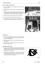
Страница 65: ...nce WA70 7 VENAM02003 2 37 Securing the articulated steering 1 Park the machine in a straight line 2 On the left side Loosen the spring pin and remove bolt 1 3 On the right side Insert the bolt 2 and...

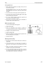
Страница 66: ...a supporting prop 1 which is to be positioned below the boom 2 Park the machine on level solid ground 3 Apply the parking brake 4 Place wheel chocks in front of the wheels to prevent the machine from...

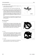
Страница 67: ...The workers must always maintain contact with each other When working near the fan fan belt or other rotating parts there is a risk of being caught in the device Ensure that you do not go too close t...

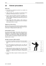
Страница 68: ...Never work under a machine that has not been sufficiently secured Keeping the machine clean Always keep the machine clean and tidy Oils grease and tools or parts laying around are dangerous because t...

Страница 69: ...r Dispose of meeting environmental standards If the machine is equipped with a fuel strainer in the tank filler port it may not be removed when adding fuel Coolant The machine is equipped with an alum...

Страница 70: ...lipping hazard and is flam mable Replace hoses every 2 years at the latest Handling high pressure oil Always keep in mind that the hydraulic circuits are under high pressure Do not add or remove oil a...

Страница 71: ...or use a cutting torch Do not hit or roll the accumulator Do not subject it to any impact Before the maintenance technician extracts the pressure accumulator the hydraulic system has to be depressuris...

Страница 72: ...ers lakes or seas Obey applicable laws and regulations when disposing of harmful objects such as oil fuel coolant solvent filters and batteries Maintaining the air conditioner If refrigerant from the...

Страница 73: ...the tyre pressure is too low the tyres may heat up and burst If the tyre pressure is too high there is also danger that the tyre may burst If a tyre heats up considerably inflammable gases are pro duc...

Страница 74: ...room that cannot be accessed by unauthorised persons Place the tyres on an even surface and incline them 60 to 70 2 against a solid stopper and secure them with wheel chocks 1 so that they cannot rol...

Страница 75: ...Operation WA70 7 VENAM02003 3 1 3 Operation...

Страница 76: ...3 1 General view Operation 3 2 WA70 7 VENAM02003 3 1 General view 3 1 1 General view of the machine 1 2 3 4 5 7 8 9 10 11 12 13 14 6...

Страница 77: ...WA70 7 VENAM02003 3 3 1 Bucket 2 Tipping lever 3 Front wheel 4 Bucket cylinder 5 Front work lights 6 Warning beacon 7 ROPS cab 8 Rear wheel 9 Turn signal 10 Headlights 11 Boom 12 Lift cylinder 13 Rear...

Страница 78: ...3 1 General view Operation 3 4 WA70 7 VENAM02003 3 1 2 Controls General view G0070202a eps 1 2 3 4 5 6 7 8 9 10 11 12 13 15 17 18 19 20 16 21 14...

Страница 79: ...7 Headlight switch 8 Horn 9 Speed range 2 switch 10 100 differential lock option 11 Direction selector switch 12 Multi function lever 13 Special equipment control lever 14 E C S S switch option 15 Aut...

Страница 80: ...3 1 General view Operation 3 6 WA70 7 VENAM02003 3 1 3 Machine monitor General view 1 2 3 4 5 6 7 8 10 9 15 14 13 11 12 16 17 19 18 G0070400...

Страница 81: ...p 5 Parking brake caution lamp 6 High beam pilot lamp 7 Direction selector switch pilot lamps 8 Turn signal pilot lamp 9 Seat belt caution lamp 10 E C S S pilot lamp 11 Rear window defroster pilot lam...

Страница 82: ...3 1 General view Operation 3 8 WA70 7 VENAM02003 3 1 4 Switches General view G0070417 G0070202a eps 1 2 3 6 7 8 13 12 14 4 11 5 9 10 16 17 15 22 20 25 27 26 19 18 21 21 23 24 28...

Страница 83: ...beacon switch option 9 Turn indicator lever 10 Light switch 11 Horn button 12 Reversing light switch 13 Sweeper switch 14 Switch for quick coupler 15 Blower switch 16 Temperature switch 17 Air condit...

Страница 84: ...or The machine monitor consists of All elements needed for the efficient operation of the machine are explained below Pilot lamps This group includes the pilot lamps for high beam glow plugs turn indi...

Страница 85: ...g Caution lamps 1 Water separator caution lamp The water separator caution lamp lights up when an excessive amount of water has accumulated in the water separator at the fuel filter If this is the cas...

Страница 86: ...aution lamp This lamp lights up when the starting switch is turned to the B ON position with the parking brake engaged If the direction selector switch is brought into the forward or reverse position...

Страница 87: ...ition At the same time the acoustic warning signal sounds With the engine running After starting the engine the engine oil pressure builds up and the lamp goes out If the lamp does not go out when the...

Страница 88: ...3 2 Descriptions of the individual elements Operation 3 14 WA70 7 VENAM02003 Pilot lamps G0070400 6 2 3 4 5 1 9 7 8...

Страница 89: ...lamp lights up when the starting switch is turned to the B ON position and the glow plugs are in operation It goes out when the pre heating is completed It is now possible to start the engine If the...

Страница 90: ...rection selector switch in F position Right arrow is lit machine travelling in reverse direction selector switch in R position If the direction selector switch is in the neutral position N both pilot...

Страница 91: ...the rear window defroster is switched on 8 Auto inch function Option This lamp lights up when the auto inch function is switched on Pressing the switch again turns off the auto inch function and the l...

Страница 92: ...available The background light is red when the fuel level is low Refill fuel If only the two bars at the right of the fuel display are lit there is no electrical contact between the fuel display and t...

Страница 93: ...he coolant temperature is nor mal The background light is red if the coolant temperature is too high The acoustic warning signal sounds If only the two bars on the right of the temperature display are...

Страница 94: ...3 2 Descriptions of the individual elements Operation 3 20 WA70 7 VENAM02003 3 2 2 Switches G0070417 G0070202a eps 1 2 3 6 7 8 13 12 14 4 11 5 9 10 16 17 15 22 20 25 27 26 19 18 21 21 23 24 28...

Страница 95: ...itch 8 Warning beacon switch option 9 Turn indicator lever 10 Light switch 11 Horn button 12 Reversing light switch 13 Sweeper switch 14 Switch for quick coupler 15 Blower switch 16 Temperature switch...

Страница 96: ...nd washer switch Use this switch to turn the windshield wiper and washer on and off The switch has two positions Position 1 is retained and turns the wiper on or off If the switch is held in position...

Страница 97: ...oming traffic Switch off the working lamps before travelling on public roads Use this switch to turn the work lights on and off 7 Rear window defroster switch Use this switch to turn the rear window d...

Страница 98: ...arch lights on and off 11 Horn button Use the horn button to sound the horn G0070269 1 2 Position 1 Left turn signal Position 2 Right turn signal 2 G0070270 0 1 2 G0070268 3 4 5 Position 0 Lights off...

Страница 99: ...se this button to unlock the quick coupler Pull the button s lock A in the direction of the arrow to unlock the button The quick coupler remains unlocked as long as the lamp is lit Releasing the butto...

Страница 100: ...he differential lock on and off As long as the button is held the differentials in the axles are locked 100 When button 1 is released the differentials are unlocked NOTICE For details see Engaging the...

Страница 101: ...tive If the machine is travelling at a speed higher than 5 km h the E C S S is activated automatically and the E C S S pilot lamp on the machine monitor lights up If the machine is travelling slower t...

Страница 102: ...nctional circuits are turned off B ON position In this position the pilot lamps are lit and the intake air pre heater is active The functional circuits are turned on The ignition key remains in this p...

Страница 103: ...u may pull it out and light a cigarette 25 Speed regulator Option The speed regulator is used to adjust the maximum ground speed of the machine in all gears within a continuous range from slow dial at...

Страница 104: ...eing replaced Never switch off the main switch while the engine is running This can lead to damage to electrical systems If the battery switch is switched off the power supply to all electrical system...

Страница 105: ...Only use this switch in emergencies This switch is used if the starting switch is off but the engine does not stop 1 Lift the cover The switch is located beneath the cover 2 Pull on the switch in posi...

Страница 106: ...levers and pedals 1 Steering column adjustment 2 Parking brake 3 Brake pedal 4 Accelerator pedal 5 Multi function lever 6 Accessory control lever 3rd control circuit and electrical quick coupler 7 Wor...

Страница 107: ...hen the parking brake is released NOTICE The machine will not start with the parking brake engaged If the direction selector switch is brought into the forward F or reverse R position with the parking...

Страница 108: ...unction lever locks in this position The floating position is used for levelling drawing off In this switching position the work equipment lowers under its own weight and moves freely due to external...

Страница 109: ...ial equipment control lever to positions 1 2 or 3 with no additional equipment attached This would cause the work equipment to operate against overpressure and heat the oil unnecessarily possibly dama...

Страница 110: ...ation 3 36 WA70 7 VENAM02003 7 Work equipment lock lever The work equipment lock lever secures the work equipment against unintended use Use this lock lever to lock the work equipment before driving o...

Страница 111: ...ock the articulated steering before lifting the machine and prior to repair and maintenance work 1 Park the machine in a straight line 2 On the left side Loosen the spring pin and remove bolt 1 3 On t...

Страница 112: ...ght to the power outlet Use the power outlet to connect a reading light 3 2 7 Door unlocking The cab doors are equipped with detents that engage when the door is fully opened 1 to prevent the door fro...

Страница 113: ...replac ing fuses only switch the battery main switch off once the green pilot lamp on the relay box has gone out Remove the key to the battery main switch Fuses with improper ratings may cause cable f...

Страница 114: ...3 2 Descriptions of the individual elements Operation 3 40 WA70 7 VENAM02003 Fuse allocation...

Страница 115: ...ndicators F2 4 10 A Monitor starting motor F2 5 10 A Monitor F2 6 20 A Work lights F2 7 10 A Parking lights F2 8 10 A Licence plate lighting F3 1 10 A Low beam F3 2 10 A High beam F3 3 10 A Solenoid s...

Страница 116: ...lown Check the electrical system and replace defective fuses When the operator s cab is tipped up the box can be found in the engine compartment on the right K238 K238 K106 100A F4 F5 G0070264A 2 1 5...

Страница 117: ...diffuser discs The upper round air outlet nozzles can be directed at the windscreen and at the side windows 1 A450 option Immobiliser 2 K56 1 Relay headlight 3 K56 2 Relay high beam 4 K67 Turn indicat...

Страница 118: ...m heating effect inside the cabin open all air outlet nozzles a set rotary switch 2 to maximum heating power and set the fan to its highest speed with rotary switch 1 To achieve a comfortable temperat...

Страница 119: ...he air conditioner 1 Open all air intake nozzles b if equipped NOTICE If the air intake nozzles are closed b the cooling capacity decreases 2 Turn the fan switch 1 to position 4 3 Turn the temperature...

Страница 120: ...equipment and the hydraulic system Also check for loose cables and accumulations of dirt Repair any defects and remove accumulations of dirt Before starting to work Perform the following tasks daily...

Страница 121: ...eck the handrails for damages and loose screws Repair damages and retighten loose screws 8 Check gauges and indicators Check all gauges and indicators for damages and loose screws Replace defective pa...

Страница 122: ...ck for loose or damaged screws Have any screws retightened or replaced by a Komatsu distributor Always retighten loose screws to the specified torque Always replace damaged screws with original parts...

Страница 123: ...ot engine Wait until the engine has cooled down before adding cool ant 1 Open the bonnet 2 Check that the coolant level in the expansion tank tank is between the MAX and MIN marks Add coolant if the c...

Страница 124: ...ed daily and cleaned if neces sary NOTICE Be careful to close the intake opening 2 of the dust pre separator before cleaning Entry of water may cause engine damage Do not hold the compressed air or wa...

Страница 125: ...f the radiator fins 1 Loosen the screws 1 and remove the fan grille to clean the radiator fins 2 Reinstall the fan grille after cleaning Check the centricity of the support pins 2 V belt check conditi...

Страница 126: ...and pull out again after a moment The oil level must be between the H and L marks on the dipstick 3 If the oil level is below the L mark add engine oil through the oil filler neck 2 See chapter 5 4 F...

Страница 127: ...tly large oil tray 1 Place the tray underneath the drain screw arrow 2 Remove the cap 1 of the drain valve 3 Screw a drain hose 2 onto the drain valve This opens the drain valve 4 Drain excessive oil...

Страница 128: ...el may ignite Immediately remove any spilled fuel 1 Turn the starting switch to the B ON position 2 Check the fuel level at the fuel gauge 3 Turn the starting switch to the A OFF position 4 Add fuel a...

Страница 129: ...d hand tighten the collar nut 6 Open the stop valve A by turning the lever downward NOTICE The two water separators are bled together at the end Water separator draining water and dirt accumulations 1...

Страница 130: ...he filter with fuel after draining to pre vent problems when starting the engine 5 Loosen the bleed screw 2 on the injection pump 6 Work the pump button 3 on the fuel filter until there are no more bu...

Страница 131: ...lit if the intake air pre heater is active NOTICE Contact your Komatsu distributor if one of the pilot lamps does not light up Do not use only the gauges and indicators for the checks before starting...

Страница 132: ...is insufficient the filter cloth in the heater air conditioner may be clogged and should be cleaned or replaced If the cooling performance of the air conditioner is too low check whether the condense...

Страница 133: ...rator s seat can be adjusted with spring support with levers 3 and 4 Use lever 3 to adjust the front section of the seat and lever 4 for the rear section Height adjustment Equally adjust the front and...

Страница 134: ...djust the backrest apply a light load to it and pull and hold lever 5 Take load off the backrest to tilt it forward Press the back rest to the rear to tilt it backward Release lever 5 when the backres...

Страница 135: ...3 Adjusting the height The seat hight can be set to several different positions Raise the seat to the desired height until you can hear it clicking into place If the seat is raised above the upper st...

Страница 136: ...wheel when sitting comfortably while at the same time having a good view of the work equipment Hold the steering wheel in this position 3 Lock the steering column in this position by applying the lock...

Страница 137: ...re starting to work and do not take it off while working Fasten the belt so that it is not twisted and fits snugly The machine is equipped with a seat belt that retracts automati cally Automatically r...

Страница 138: ...rning signal sounds The fuel level is displayed 1 The parking brake caution lamp 2 lights if the parking brake is engaged The caution lamps for battery charge circuit 3 and engine oil pressure 4 are l...

Страница 139: ...details see 3 5 Operation in cold weather 3 105 Ambient temperature for operation and storage The recommended ambient temperature for operation and stor age is between 20 C and 45 C For ambient tempe...

Страница 140: ...ctioning of all hydraulic cylinders with the multi function lever Verify the proper functioning of the steering To warm up the hydraulic oil repeatedly tip the multi function lever for the work equipm...

Страница 141: ...ensure that there are no persons in the area surrounding the machine and sound the horn 1 Start the engine as described in chapter 3 3 2 Starting the engine 3 64 2 Raise the work equipment to the car...

Страница 142: ...Stop the machine 2 Initially set the speed regulator to the lowest speed To do so turn the speed regulator 1 all the way to the left stop 0 position 3 Depress the accelerator pedal The machine stays s...

Страница 143: ...the horn 1 Start the engine as described in chapter 3 3 2 Starting the engine 3 64 2 Apply the parking brake The parking brake caution lamp lights up 3 Depress the brake pedal 4 Release the parking b...

Страница 144: ...op before changing direction Use the direction selector switch to switch between forward and reverse The machine may still be coasting when the direction is reversed Driving in reverse The back up lig...

Страница 145: ...e may fall over or slip when operated too close to steep slopes ridges or embankments The limit values are listed in chapter 6 4 Limit values for slopes 6 6 Do not turn or traverse on slopes Only exec...

Страница 146: ...arking brake lever 4 Release the lock button The parking brake pilot lamp goes out Braking with the service brake If the deceleration by releasing the accelerator pedal is insuffi cient use the servic...

Страница 147: ...on slopes ATTENTION When travelling downhill for extended periods of time the service brake may overheat and become damaged Keep the engine running when driving downhill Use the brake in addition when...

Страница 148: ...e ground WARNING Inadvertently operating the multi function lever or moving the work equipment may cause accidents Engage the work equipment lock lever before leaving the operator s cab 5 Engage the w...

Страница 149: ...tion The floating position is used for levelling drawing off In this switching position the work equipment lowers under its own weight and moves freely due to external force S Lower This switch positi...

Страница 150: ...d end of the rod 2 is in line with the centre of the sensing surface of the proximity switch 3 Tighten the screws to lock the bracket in position Set the gap between the rod 2 and the sensing surface...

Страница 151: ...ds the greatest digging force and lowest tyre wear Drive slowly when clearing away stockpiled material or load ing blasted rock speed range 1 When digging raise the bucket when entering the stockpile...

Страница 152: ...ferential lock To engage the differential lock press and hold button 1 on the multi function lever The differential lock may only be switched on when the machine is stopped If only one wheel of an axl...

Страница 153: ...rdan shaft Always drive the machine into the material in a straight line Observe the instructions in section Saving the tyres 3 77 when digging 1 Drive the machine into the stockpiled soil in a straig...

Страница 154: ...g tyre slip and increased tyre wear Always keep the load at the centre of the bucket An uneven load distribution may impair the machine s balance 6 Raise the boom while entering the material to preven...

Страница 155: ...achine with the service brake while keeping the accelerator pedal depressed 3 Slightly tilt the bucket downwards 4 While driving forward move the multi function lever for the boom slightly towards LOW...

Страница 156: ...After filling in the holes you may level the ground ATTENTION Danger of accidents Carelessly driving in reverse may cause severe accidents Check that there are no persons behind the machine before st...

Страница 157: ...ood condition and that there are no persons in the way Remove fallen rocks from the working area Keep the bucket tilted in Lower the boom to the carrying position For details see Saving the tyres 3 77...

Страница 158: ...the machine at right angles to the stockpile Back the machine up in a straight line after filling the bucket Then wait for the dump lorry to move between the stockpile and the machine Drive forward to...

Страница 159: ...r 2 2 General precautions 2 9 Do not pick up loads that are so high as to block the opera tor s view of the route Hold the tines of the forklift attachment horizontally when picking up a load While dr...

Страница 160: ...so the load con tacts the back of the forklift attachment 3 Slightly tilt the forklift attachment to prevent the load from slipping off 4 Lower the boom to the carrying position 5 Raise the load to t...

Страница 161: ...in section Working on snow 2 28 Dumping on steep slopes Follow the instructions in section While loading 2 27 Working near high voltage cables Follow the instructions in section Working near high vol...

Страница 162: ...Operation 3 46 Fasten any manual tools before starting to drive The required tyre pressure the ground speed and the type of tyre vary depending on the road conditions Contact your Komatsu distributor...

Страница 163: ...pment control lever to position 1 while pressing and holding button 4 3 Slightly raise the boom by setting the multi function lever to position H 4 Slightly tilt the quick coupler forward Push the mul...

Страница 164: ...ork equipment contact the quick coupler 7 Lock the quick coupler by setting the special equipment con trol lever to position 2 The locking bolts b must be visible WARNING If the work equipment is not...

Страница 165: ...ydraulic lines of the multi purpose bucket to quick couplers 5 and 6 12 Start the engine Now the multi purpose bucket can be operated with the spe cial equipment control lever WARNING If the work equi...

Страница 166: ...special equipment control lever to position 1 while pressing and holding button 4 3 Use the multi function lever to set the quick coupler to the dump position A until the quick coupler disengages from...

Страница 167: ...quipment control lever to position 1 while pressing and holding button 4 7 Use the multi function lever to set the quick coupler to posi tion A until the quick coupler disengages from the mounting hoo...

Страница 168: ...load at a medium speed for 5 minutes before switching it off so that the engine can cool down 3 Lower the working equipment 4 Turn the starting switch to the A OFF position to stop the engine 5 Remove...

Страница 169: ...Operation 3 3 Operation WA70 7 VENAM02003 3 95 3 3 15 Locking Lock at the following locations NOTICE The ignition key fits all locks 1 2 1 Engine bonnet 2 Cab door...

Страница 170: ...he tyre pressure does not drop below 2 bar If the tyre inflation pressure is too low there will be overload if it is too high it will cause tyre cuts and shock burst As a general principle for visual...

Страница 171: ...the tyres against damage Do not deflate the tyres if the pressure increases due to high temperature Check and adjust the tyre pressure before starting to work when the tyres are cold Under extreme op...

Страница 172: ...achine Keep a sufficient distance from the road shoulder Use ramps of ample width length thickness and strength Install the ramps with an inclination of less than 15 When using an embankment compact t...

Страница 173: ...en fix the ramps in line with the centres of the trailer and the machine Check that both sides are of equal height The ramp s angle of inclination must not exceed 15 Set the distance between the ramps...

Страница 174: ...opes and wheel chocks or wedges to prevent it from sliding or falling off Secure the machine to the trailer as follows 1 Set the direction selector switch to the neutral position N 2 Apply the parking...

Страница 175: ...ly when transporting frequently 6 Put wheel chocks in front of and behind the wheels Secure the machine with chains or wire ropes to prevent it from moving during transport Be especially careful to en...

Страница 176: ...height The ramp s angle of inclination must not exceed 15 Set the distance between the ramps to match the centre of the tyres If the ramp sags noticeably reinforce it with blocks or similar 3 Remove...

Страница 177: ...fore lifting the machine Engage the work equipment lock lever Danger of injury Objects placed on the machine may drop when the machine is lifted Remove all loose objects from the machine before liftin...

Страница 178: ...e diagram above The slings ropes chains or similar may only be used up to a maximum angle of 10 see illustration above and must not touch any part of the machine aside from the attachment points Lift...

Страница 179: ...f antifreeze should contact your eyes or skin wash it off with a large amount of fresh water and see a doctor at once When changing the coolant or when handling coolant con taining antifreeze that has...

Страница 180: ...e on solid dry ground If this is impossible park the machine on wooden boards The boards prevent the wheels from freezing to the ground so the machine will be able to move the next morning Open the dr...

Страница 181: ...re from accumulating Lubricate the machine and change the oil before storage Coat the exposed portion of the hydraulic cylinder rod with grease Switch off the engine Turn the starting switch to the OF...

Страница 182: ...ring this operation Check the refrigerant level twice a year If the machine is equipped with a central lubrication system intermediate lubrication must be carried out every month 3 6 3 After storage N...

Страница 183: ...be removed or rendered inopera ble If these precautions are not followed neither Komatsu nor your Komatsu distributor will be liable for any resulting problems or losses 3 7 1 Basic precautions WARNIN...

Страница 184: ...also stopped Please contact your Komatsu distributor before installing a top guard or any other attachment that covers the cab roof Be careful to prevent water from spilling on the communica tions te...

Страница 185: ...Troubleshooting WA70 7 VENAM02003 4 1 4 Troubleshooting...

Страница 186: ...Before you are permitted to tow a machine that is equipped with a hydrostatic drive you have to establish a short circuit connec tion between the high pressure side and the low pressure side of the v...

Страница 187: ...ut 2 and screw in the threaded pin 3 clockwise by means of an Allen key until it is level with the top of the lock nut 4 Retighten the lock nut 2 Perform this task on both valves Version B Hold the va...

Страница 188: ...ockwise by means of an Allen key all the way Retighten the lock nut 2 Perform this task on both valves Version B Hold the valve 1 with a wrench Loosen the lock nut 2 and screw the threaded pin 3 clock...

Страница 189: ...es to tow a machine with defective brakes Connect the three machines with appropriate towing devices If you intend to tow a machine with defective brakes or the machine has to be towed downhill you ne...

Страница 190: ...ck of the defective machine spark formation occurs here Therefore perform the connection at a spot that is as far away as possible from the battery Be careful when disconnecting the cable from the sta...

Страница 191: ...follows in the sequence of the numbers in the illustration 1 Connect a terminal of the booster cable A to the positive terminal of the defective machine 2 Connect the other terminal of the booster ca...

Страница 192: ...ooster cables When the engine has started remove the booster cables in the opposite order of connecting 1 Disconnect the terminals of the booster cable B from the frame of the defective machine 2 Disc...

Страница 193: ...tsu distributor 4 3 2 Checking the parking brake 1 Start the engine align the machine forward and drive the machine up a 25 slope with an empty bucket 2 Stop the machine with the service brake and hol...

Страница 194: ...4 4 Emergency steering properties If the engine fails while you are driving you can still steer the machine However you need to manually apply more power In case of engine failure immediately drive to...

Страница 195: ...nstalled the machine is equipped with a pressure accumulator so that the work unit can be lowered by means of the multi function lever when the diesel engine is off NOTICE If you have locked the work...

Страница 196: ...ons and cables Alternator is not functioning Check the function of the alternator replace defective alternator Drive belts of the alternator are not tensioned properly Tension drive belt Alternator cr...

Страница 197: ...g ratio Coolant level too low Coolant system leaky Check lines and hoses visual inspec tion discharge of coolant Replace defective lines and hoses The background of the temperature display lights up i...

Страница 198: ...too low Check valve clearance Combustion sounds like breathing intermittently Injection nozzles defective Replace injection nozzles Abnormal combustion noises Wrong fuel Use prescribed fuel Engine tem...

Страница 199: ...se valve is defective Check the forward reverse valve Replace the defective forward reverse valve Switch relay is not functioning Check the function of the switch relay repair or replace a defective s...

Страница 200: ...T continued Fault Cause Remedy WORK EQUIPMENT Fault Cause Remedy Lifting power too low Hydraulic pump is defective Directional valve DBV is defective Cylinder is defective leaks inside Repair the hydr...

Страница 201: ...ut Replace brake pads Replace brake disc Air in the brake system Bleed the brake system Brake oil level caution lamp Brake oil level caution lamp goes on Brake oil level in the brake oil con tainer to...

Страница 202: ...f errors occur that are not listed here have the repair performed by your Komatsu distributor STEERING Fault Cause Remedy Steering reacts sluggish Hydraulic system is not working properly Check the fu...

Страница 203: ...Maintenance WA70 7 VENAM02003 5 1 5 Maintenance...

Страница 204: ...performing main tenance Always position the machine as specified for maintenance and repairs Unless explicitly specified otherwise the machine must be posi tioned as follows Lower the work equipment t...

Страница 205: ...ing the articulated steering 2 37 NOTICE The machine has to be positioned as for driving in a straight line and the articulated steering has to be secured with the locking bolt If the operator s cab i...

Страница 206: ...he cab upward until it reaches the limit stop 9 Fold out the safety rod on the right side over the retaining pin 10 Set the lever at the pump to pump down and pump the cab downward until the safety ro...

Страница 207: ...nd pump the cab upward until it reaches the limit stop 2 Fold in the safety rod on the right side and secure it in the folded position arrow 3 Set the lever to pump down and pump the cab downward unti...

Страница 208: ...e Komatsu genuine oils and grease Choose oils and grease with proper viscosities specified for ambient temperature Always use clean washer fluid Use ethanol based window washer fluid and ensure it is...

Страница 209: ...not to drop screws nuts or tools into the machine If such objects are dropped into the machine they will dam age the machine and cause malfunctions leading to machine failure If you drop anything ins...

Страница 210: ...r repairing or replacing parts or lines of the hydraulic circuit it is necessary to bleed the air from the circuit Precautions when installing hydraulic hoses When removing parts with sealing rings or...

Страница 211: ...become caught in the lever linkage Is there any leakage of water or oil Have all the bolts been tightened Checks with the engine running If a maintenance task must be carried out with the engine runni...

Страница 212: ...n the piping mixes with the new oil Unless specifically required otherwise the machine is deliv ered with fuel coolant and lubricants as shown in the table below Component Type Engine oil pan EO15W40D...

Страница 213: ...re caused by such impurities Take particular care to prevent contamination during storage or when refilling Never mix oils of different grades or brands Always add the specified amount of oil Both too...

Страница 214: ...viscosity will decrease This may cause a loss of output performance To prevent the moisture in the air from condensing and form ing water inside the fuel tank always fill the fuel tank after completi...

Страница 215: ...h as a river water or well water hard water contains large amounts of minerals calcium magne sium etc This accelerates the formation of scale inside the engine or the radiator Once present scale is ve...

Страница 216: ...ess or screeching Always wipe off all of the old grease that is pushed out when greasing Be particularly careful to wipe off the old grease in places where sand or dirt sticking in the grease would ca...

Страница 217: ...ing used Never try to clean filters cartridge type and use them again Always replace with new filters When replacing oil filters check if the old filter contains any metal particles If any metal parti...

Страница 218: ...electrical components The maintenance of the electrical system involves checking fan belt tension checking the fan belt for damage or wear and checking the battery fluid level Never install any elect...

Страница 219: ...ts in parentheses need to be replaced at the same time Order numbers for the parts See the Parts Book Komatsu Item Part no Part name Quantity Replacement interval Option Additional water separator Fue...

Страница 220: ...A70 7 VENAM02003 5 4 Fuel lubricants and coolants quantities 5 4 1 Lubrication table The maintenance schedule in the Operation and Maintenance Manual is binding see 5 7 Maintenance schedule 5 24 Lubri...

Страница 221: ...API GL4 API GL4 API GL4 API GL 5 API GL4 API GL4 SAE 80 SAE 80 SAE 80 SAE 80W 90 SAE 10W 30 SAE 10W 30 1 Hydraulic system Steering Hydraulic oil HYD Komatsu HO46 HM 20 C to 50 C ISO VG 46 Power train...

Страница 222: ...WA70 7 VENAM02003 Tank capacity Specification litres Refill amount Engine oil pan 7 5 7 Transmission 1 3 Hydraulic system 50 Front and rear axles per axle Planetary gear 2 0 7 Differential 7 0 Brakes...

Страница 223: ...ties Maintenance WA70 7 VENAM02003 5 21 5 4 2 Recommended brands recommended quality for products other than Komatsu genuine oil Please contact your Komatsu distributor when using commer cially availa...

Страница 224: ...o Comment 1 Double ended ring span ner kit 42T 09 H0450 42T 09 H0460 42T 09 H0470 42T 09 H0440 Spanner widths 8 10 mm 13 15 mm 17 19 mm 24 27 mm 2 Screwdriver 421 98 H1120 3 Screwdriver 421 98 H1110 6...

Страница 225: ...ult to determine the extent of wear or deterioration during peri odic maintenance Hence it is required to replace these parts regardless of their condition after a certain period of usage This is impo...

Страница 226: ...ear axle 5 38 5 8 4 Maintenance after the first 250 service hours 5 39 Valve clearance check and adjust 5 39 5 8 5 Maintenance after the first 500 service hours 5 39 Front and rear axle change oil 5 3...

Страница 227: ...rs 5 60 Alternator v belt check and adjust tension 5 60 Service brake check change brake fluid 5 61 System pressures check and adjust 5 61 Hydraulic system change venting filters 5 62 Hydraulic system...

Страница 228: ...diator fins V belt check condition Check engine oil level add engine oil Check the fuel level add fuel Additional water separator optional check for sediments Water separator draining water and dirt a...

Страница 229: ...r ready for collecting the fluid from the water separator 2 Close the stop valve 1 by turning the lever upward 3 Release the collar nut 2 and remove the glass container 3 4 Empty the glass container a...

Страница 230: ...e cooling performance of the air conditioner is too low check whether the condenser is dirty Clean a dirty condenser with cold water If the water pressure is too high the fins may warp Keep a suffi ci...

Страница 231: ...as shown in the dia gram on the right the condition is normal When the air condi tioner is switched on you will see a few bubbles After this the liquid takes on a translucent milky white colour If th...

Страница 232: ...e alternator may be damaged by peak voltages Before charging remove all stoppers from the battery open ings to ensure sufficient ventilation To prevent gas explosions do not bring fire near the batter...

Страница 233: ...31 Cleaning the air grille Clean the air grilles from both sides if they are dirty NOTICE Do not use a high pressure cleaner to clean the air grilles Cleaning the radiator fins Clean the radiator fin...

Страница 234: ...rventions If the air cleaner is not sufficiently clean the air cleaner cau tion lamp 1 on the main screen will indicate a malfunction The engine power will decrease Design of the air cleaner The air c...

Страница 235: ...e severe injuries Do not work in the engine com partment while the engine is running 1 For maintenance work park and secure the machine as described in chapter 5 1 Maintenance guide 5 2 2 Open the bay...

Страница 236: ...eaning the filter inserts with pressur ised air Hazardous dusts may cause lung irritation Wear a dust mask when cleaning filter inserts with pressur ised air Blow out the air cleaner insert with dry p...

Страница 237: ...er inserts for damaged seals NOTICE Also check any new filter inserts before installing Installing the filter insert 1 Check the safety filter for firm seat 2 Insert the filter insert into the housing...

Страница 238: ...w air cleaner for damage by shining a light through it 3 Install the filter insert Changing the safety filter NOTICE Do not clean the safety filter Replace it every third time the filter insert is cha...

Страница 239: ...r details see Hydraulic system change venting filters 5 62 Wheel nuts check and retighten WARNING Loose wheel nuts may cause severe accidents Periodically check and retighten the wheel nuts Loose whee...

Страница 240: ...at is not properly parked and secured may cause severe accidents Park the machine on solid level ground Secure the machine before beginning maintenance work 1 For maintenance work park the machine as...

Страница 241: ...first 250 ser vice hours Valve clearance check and adjust Have the valve clearance checked and adjusted by a Komatsu distributor 5 8 5 Maintenance after the first 500 service hours Carry out the follo...

Страница 242: ...ine on solid level ground Secure the machine before beginning maintenance work 1 For maintenance work park the machine as described in chapter 5 1 Maintenance guide 5 2 2 Clean the grease nipples indi...

Страница 243: ...o not smoke 1 For maintenance work park and secure the machine as described in chapter 5 1 Maintenance guide 5 2 2 Check the battery and terminals for firm seat 3 Clean the area around the stoppers 4...

Страница 244: ...e before beginning maintenance work 1 For maintenance work park the machine as described in chapter 5 1 Maintenance guide 5 2 2 Clean the indicated grease nipples 3 Use a grease pump to press a suffic...

Страница 245: ...5 8 Maintenance procedure Maintenance Maintenance every 50 service hours WA70 7 VENAM02003 5 43 G0070247 G0070248 1 2 5 5 6 3 4...

Страница 246: ...ubricants Grease of NLGI class 2 with EP additives compatible with plas tics NBR elastomers copper and copper alloys and a max flow pressure of 700 mbar Fill the lubricant container to above the MIN m...

Страница 247: ...s WARNING Danger of accidents If the brake oil level is too low the service brake might fail ATTENTION Danger of accidents Using commercially available brake fluid may reduce the performance of the br...

Страница 248: ...n chapter 5 1 Maintenance guide 5 2 2 Press the v belt inward in the middle of the longest straight section When pressed the v belt should move inward by about 10 15 mm If the v belt can be pressed in...

Страница 249: ...parked and secured may cause severe accidents Park the machine on solid level ground Secure the machine before beginning maintenance work 1 For maintenance work park the machine as described in chapt...

Страница 250: ...not properly parked and secured may cause severe accidents Park the machine on solid level ground Secure the machine before beginning maintenance work 1 For maintenance work park the machine as descr...

Страница 251: ...5 8 Maintenance procedure Maintenance Maintenance every 250 service hours WA70 7 VENAM02003 5 49 Wheel nuts check and retighten For details see Wheel nuts check and retighten 5 37...

Страница 252: ...every 10 50 100 and 250 service hours Manual pump check oil level 1 The oil level in the hand pump is checked with the cab tipped down 2 Remove the screw plug 1 3 The oil level should be at the lower...

Страница 253: ...educe the performance of the brake system Only fill with the specified oil Do not use brake fluid Keep extremely clean All repairs of the brake system have to be performed by a Komatsu distributor 1 F...

Страница 254: ...may cause severe accidents Park the machine on solid level ground Secure the machine before beginning maintenance work NOTICE Change the oil only with the engine off and at operating temper ature 1 Fo...

Страница 255: ...ontact the filter holder lightly Then tighten the filter cartridge as specified by the filter manufacturer 4 After changing the filter cartridge fill clean engine oil through the oil filler neck 2 unt...

Страница 256: ...Use the filter wrench to unscrew the filter cartridge anticlock wise 5 Unscrew and remove the sensor 3 and o ring 4 from the fuel filter 6 Screw the sensor 3 and with a new o ring 4 onto the new fuel...

Страница 257: ...gog gles and rubber gloves when working on the injection pump In the event of being hit by a high pressure fuel jet immediately consult a doctor For maintenance work park and secure the machine as des...

Страница 258: ...Remove the filter cloth 2 from the heater 3 3 Clean the filter cloth in warm water 30 40 C added with a mild detergent Caution Do not rub or wring the filter cloth 4 Dry the filter cloth 5 Insert the...

Страница 259: ...enser with cold water If the water pressure is too high the fins may warp Keep a suffi cient distance when cleaning with a high pressure washing machine Checking the gas pressure in the pressure accum...

Страница 260: ...er the work equipment and apply the parking brake 2 Remove the screw plug 1 from the check bore 3 Check the oil level The oil level should be at the lower edge of the check bore 4 If the oil level is...

Страница 261: ...on a machine that is not properly parked and secured may cause severe accidents Park the machine on solid level ground Secure the machine before beginning maintenance work 1 For maintenance work park...

Страница 262: ...ne compartment may cause severe injuries Do not work in the engine compartment while the engine is run ning 1 For maintenance work park and secure the machine as described in chapter 5 1 Maintenance g...

Страница 263: ...reduce the performance of the brake system Only fill with the specified oil Do not use brake fluid Keep extremely clean All repairs of the brake system have to be performed by a Komatsu distributor F...

Страница 264: ...raulic oil that has come into contact with the skin Use only the prescribed supporting prop to support the work unit Never use other objects as supports 1 Lower the work equipment to the ground 2 Park...

Страница 265: ...ow the boom if the boom is supported 4 Position the supporting prop underneath the boom 5 With the engine switched off lower the boom slowly until it rests safely on the supporting prop 6 Loosen the v...

Страница 266: ...before beginning maintenance work Epicyclic gearing 1 Start the engine raise the work equipment and move the machine until the screw plug 1 of the epicyclic gearing on the wheel to be checked is at t...

Страница 267: ...of the drain holes 2 and the two screw plugs of the filling and check bores 1 Drain the oil 3 Clean the screw plugs and install an intact seal 4 Insert the screw plugs 2 and tighten firmly 5 Fill in o...

Страница 268: ...perly parked and secured may cause severe accidents Park the machine on solid level ground Secure the machine before beginning maintenance work Provide a sufficiently large drain tray 1 For maintenanc...

Страница 269: ...ding antifreeze Park the machine on solid level ground before cleaning the cooling system or changing the coolant Clean the inside of the cooling system change the coolant and the anti corrosive accor...

Страница 270: ...osive properties of Supercoolant AF NAC always keep the proportion of Supercoolant between 30 and 60 When deciding the ratio of antifreeze to water check the lowest temperature in the past and use the...

Страница 271: ...enclosed air may not be able to escape fully After filling wait for three more min utes and top off fluid if required 1 Slowly fill the cooling system with the cleaning agent Observe the instructions...

Страница 272: ...g system remove the radiator cap and let the engine run at low idle for five minutes then for another five minutes at high idle If the coolant level in the radiator drops add coolant 5 Switch off the...

Страница 273: ...th the skin Danger of scalding The hydraulic reservoir is pressurised Hot hydraulic oil may spurt out and cause scalding Wear rubber gloves and hold the oil drain tray underneath the drain in a way th...

Страница 274: ...rew the venting filter 1 11 Fill with oil until the oil level is between the centre and the upper edge of the sight glass 12 Screw in the venting filter 1 13 Start the engine 14 Repeatedly raise and l...

Страница 275: ...73 Check fuel pump Have the fuel pump checked by your Komatsu distributor Fuel and coolant hoses check replace if required Have the fuel and coolant hoses checked and replaced if required by your Kom...

Страница 276: ...5 8 Maintenance procedure Maintenance every 2000 service hours Maintenance 5 74 WA70 7 VENAM02003...

Страница 277: ...Technical data WA70 7 VENAM02003 6 1 6 Technical data...

Страница 278: ...e power 36 9 kW ISO 14396 Torque max 180 Nm Starter motor 12 V 2 2 kW Alternator 12 V 90 A Battery 100 Ah Driving speed forward and reverse Standard version 1nd speed range 2nd speed range 0 7 km h 0...

Страница 279: ...rdance with ISO 11201 the greatest value for the standard deviation of the average measured A rated acous tic pressure level at the operator s seat is A dB Acoustic power level generated by the machin...

Страница 280: ...ement procedures that are defined in the standards ISO 2631 1 and ISO 5349 Operating conditions Wheel loader V shape loading Guide to reduce vibration levels on machine The following guides can help a...

Страница 281: ...own when it is necessary to go over rough terrain Make the curve radius of travelling path as large as pos sible Travel at low speed when travelling around sharp curves 7 Minimise vibrations for long...

Страница 282: ...t which the machine at rest can stand on a slope without tipping over You must not work with the machine at these angles as the motor transmission hydraulic system or axles will not be sup plied with...

Страница 283: ...Special equipment attachments WA70 7 VENAM02003 7 1 7 Special equipment attachments...

Страница 284: ...ator and the solenoid valve When the E C S S is activated the solenoid valve opens and the circuit at the piston head of the lift cylinder is connected to the pressure accumulator 7 1 2 Precautions wh...

Страница 285: ...vated automatically and the E C S S pilot lamp on the machine monitor lights up If the machine is travelling at a speed lower than 5 km h the E C S S system is deactivated and the pilot lamp on the ma...

Страница 286: ...indicator shows the status of the bucket NOTICE When the quick coupler is dismounted the clamp at the piston rod C and indicator rod D have to be dismounted as well Else the cylinder seal could be da...

Страница 287: ...lubrication points connected to the machine 7 3 1 Changing the lubrication intervals and duration The central lubrication system is preset for normal use The settings have been preset in the factory...

Страница 288: ...1 Turn the starting switch to the B ON position This switches on the lubrication pump 2 Observe the grease container When the paddle agitator operates in the grease container the lubricating system is...

Страница 289: ...ed and remounted afterwards LED display Buttons G0070304 1 2 3 4 5 6 1 Three digit LED display Values and operational condition 2 Intermission sequence 3 Pump operation 4 Monitoring the system functio...

Страница 290: ...ich the pump is pumping Input and display value in minutes c COUNTER CO CONTACT Caution Do not use This mode triggers a malfunction C Cycle O OFF P Pressure Display of the start of the menu Monitoring...

Страница 291: ...Index WA70 7 VENAM02003 8 1 8 Index...

Страница 292: ...rette lighter 3 29 control lever additional functions 3 77 control levers special equipment 3 35 controls 3 4 caution lamps 3 11 control levers 3 32 gauges 3 18 general view 3 4 pedals 3 32 pilot lamp...

Страница 293: ...ngine oil change 5 52 front axle checking oil level 5 58 oil change 5 64 fuel and coolant hoses 5 73 fuel filter changing filter cartridge 5 54 heater air conditioner cleaning renewing filter cloth 5...

Страница 294: ...tyres 2 45 safety instructions asbestos 2 20 leaving the machine 2 11 loading 2 27 pressure accumulator 2 43 safety clothing 2 9 workplace 2 16 safety labels 1 7 2 2 safety critical parts 5 23 serial...

Страница 295: ...rrying 3 83 forklift attachment 3 85 levelling 3 82 loading 3 79 near high voltage cables 2 17 on snow 2 28 saving the tyres 3 77 V vibration levels 6 4 W wear parts list 5 17 weights machine 1 22 win...

Страница 296: ...8 1 Index Index 8 6 WA70 7 VENAM02003...

Страница 297: ...Notes WA70 7 VENAM02003 9 1 9 Notes...

Страница 298: ...Notes 9 2 WA70 7 VENAM02003...

Страница 299: ...Notes WA70 7 VENAM02003 9 3...

Страница 300: ...Notes 9 4 WA70 7 VENAM02003...

Страница 301: ...Notes WA70 7 VENAM02003 9 5...

Страница 302: ...Notes 9 6 WA70 7 VENAM02003...

Отзывы: