


5
×
NO.0080
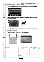
Adjustment of rear view monitor guide line
position
6
×
Assembly procedure
②
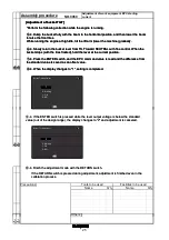
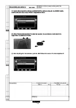
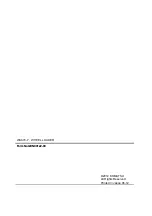
While "Horizontal Adjustment" is selected, operate the Luminance control switch to adjust
the X coordinate of Point 4.
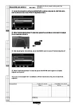
①
Select [Point 4] with the UP (
▲
) and DOWN (
▼
) switches and press the ENTER switch,
and the screen moves to the "Point 4" adjustment screen.
Q'ty
Name
Q'ty
Others
3
×
Precautions
Tools to be used
Name
Facilities to be used
4
×
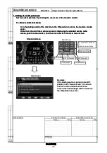
②
While "Horizontal Adjustment" is selected, operate the Luminance control switch to adjust
the X coordinate of Point 4.
①
Select [Point 4] with the UP (
▲
) and DOWN (
▼
) switches and press the ENTER switch,
and the screen moves to the "Point 4" adjustment screen.
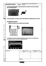
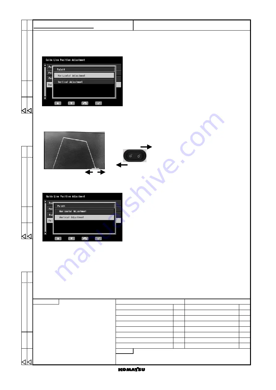
③
After adjusting the X-coordinate, press the ENTER switch to select "Vertical Adjustment".
*As a rule, do not adjust the Y-coordinates of Point 3 and 4 since they do not need to be
adjusted.
④
While "Vertical Adjustment" is selected, press the ENTER switch again to complete
adjustment of point 4.
Others
1 ×
2 ×
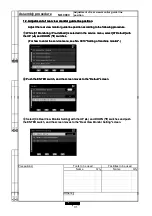
②
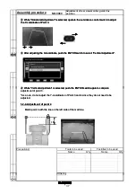
While "Horizontal Adjustment" is selected, operate the Luminance control switch to adjust
the X coordinate of Point 4.
①
Select [Point 4] with the UP (
▲
) and DOWN (
▼
) switches and press the ENTER switch,
and the screen moves to the "Point 4" adjustment screen.
③
After adjusting the X-coordinate, press the ENTER switch to select "Vertical Adjustment".
*As a rule, do not adjust the Y-coordinates of Point 3 and 4 since they do not need to be
adjusted.
④
While "Vertical Adjustment" is selected, press the ENTER switch again to complete
adjustment of point 4.
38
Содержание WA470-7
Страница 1: ...WHEEL LOADER Field Assembly Instruction GEN00122 00 WA470 7 SERIAL NUMBERS 10001 and up...
Страница 3: ......
Страница 42: ......


