background image

Adjustment of rear view monitor guide line
position

 6

 ×

Assembly procedure

 5

 ×

NO.0080

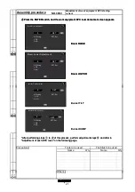
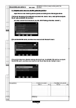
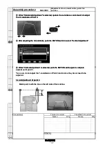
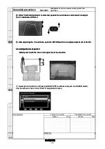
While "Horizontal Adjustment" is selected, operate the Luminance control switch to 

adjust the X coordinate of Point 2.

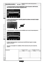
Select [Point 2] with the UP (

) and DOWN (

) switches and push the ENTER switch, 

and the screen moves to the "Point 2" adjustment screen.

Q'ty

Name

Q'ty

Others

Tools to be used

Name

Facilities to be used

 4

 ×

Precautions

 3

 ×

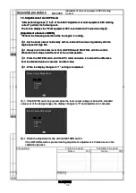
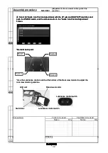
While "Horizontal Adjustment" is selected, operate the Luminance control switch to 

adjust the X coordinate of Point 2.

Select [Point 2] with the UP (

) and DOWN (

) switches and push the ENTER switch, 

and the screen moves to the "Point 2" adjustment screen.

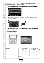
After adjusting the X-coordinate, push the ENTER switch to select "Vertical Adjustment".

Others

 1 ×

 2 ×

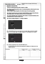
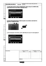
While "Horizontal Adjustment" is selected, operate the Luminance control switch to 

adjust the X coordinate of Point 2.

Select [Point 2] with the UP (

) and DOWN (

) switches and push the ENTER switch, 

and the screen moves to the "Point 2" adjustment screen.

After adjusting the X-coordinate, push the ENTER switch to select "Vertical Adjustment".

35

Содержание WA470-7

Страница 1: ...WHEEL LOADER Field Assembly Instruction GEN00122 00 WA470 7 SERIAL NUMBERS 10001 and up...

Страница 2: ...pment controller boom angle 1 4 to 4 4 11 0050 Adjustment of work equipment EPC lever detent position 1 5 to 5 5 15 0060 Adjustment of work equipment EPC starting current 1 6 to 6 6 20 0070 Adjustment...

Страница 3: ......

Страница 4: ...ments When implementing the initial setting or option setting of the sensor you must access the service mode of the machine monitor before starting the operation 1 1 How to enter Service Menu 1 1 1 Op...

Страница 5: ...machine monitor Press the ENTER switch and the screen moves to the Abnormality Record screen Select 02 Electrical Systems with the UP and DOWN switches and press the ENTER switch and the screen moves...

Страница 6: ...e unified failure code 6 digits 4 Indicates the failure code 5 Indicates the number of occurrences of the abnormality 6 Indicates the service meter reading when the abnormality occurred for the first...

Страница 7: ...t an abnormality record that you desire to delete with the UP and DOWN switches and press the ENTER switch and the screen moves to the Electrical Sys Error Reset screen Press the ENTER switch and the...

Страница 8: ...ms screen Check that all the records have been deleted On the Electrical Systems screen press the 1 2 and AUTO3 numeral keys in order while holding down the DOWN switch and the ENTER switch and MENU s...

Страница 9: ...Press the ENTER switch and the screen moves to the Default screen Select 02 Option Select with the UP and DOWN switches and press the ENTER switch and the screen moves to the Option Select screen Sele...

Страница 10: ...mergency Steering ADD If option is not installed select NO ADD J S or FNR SWITCH NON When MF lever or right FNR forward reverse switch is installed select OPT FNR Lift Up Mode ADD Set ADD and do not c...

Страница 11: ...type set with the Work Equipment Control Semi auto Digging Load Meter Boom Model TYPE A Main valve type 2 spool valve Lever type 2 lever TYPE B Main valve type 2 spool valve Lever type MF lever TYPE...

Страница 12: ...omatically 1 4 Selection of setting no setting of options Change each item which is applicable to setting no setting selection in the Optional component installation setting table by the following set...

Страница 13: ...rks After if the starting switch is turned to the ON position without waiting for 15 seconds an error warning alert is displayed If an error warning alert is displayed turn the starting switch to the...

Страница 14: ...the service menu see No 0010 Setting of machine monitor Press the ENTER switch and the screen moves to the Adjustment screen Select 06 Boom Angle Sensor for EPC Raise with the UP and DOWN switches and...

Страница 15: ...e and then adjust the angle sensor again Boom Angle Sensor for EPC Raise 0 SET 0 Waiting 1 OK 2 NG SET Set If the display changes to 2 the boom angle voltage is out of specification and adjustment is...

Страница 16: ...NTER switch to finish the adjustment mode If the RETURN switch is pressed during adjustment adjustment is finished even in the calibration process If the display changes to 2 the boom angle voltage is...

Страница 17: ...ties to be used 4 If adjustment is not performed check the boom angle sensor by monitoring Adjust the boom angle sensor installation position so that the voltage displayed by monitoring is in the foll...

Страница 18: ...ter the service menu see No 0010 Setting of machine monitor Press the ENTER switch and the screen moves to the Adjustment screen Select a work equipment EPC adjustment item from adjustment items No 08...

Страница 19: ...owing page Press the ENTER switch and the work equipment EPC lever detent set screen appears Boom Raise Adjustment 0 0 Waiting 1 OK 2 NG SET Set SET SET Boom Lower Adjustment 0 0 Waiting 1 OK 2 NG SET...

Страница 20: ...lever detent set in previous step Adjustment of boom RAISE detent position Boom Raise Adjustment 1 0 Waiting 1 OK 2 NG 1 If the ENTER switch is pressed while the lever output voltage is below the sta...

Страница 21: ...Adjustment of boom LOWER FLOAT detent position Boom Lower Adjustment 1 0 Waiting 1 OK 2 NG 2 If the ENTER switch is pressed while the lever output voltage is below the standard value out of the desig...

Страница 22: ...ed Adjustment of bucket tilt detent position Bucket Tilt Adjustment 1 0 Waiting 1 OK 2 NG 3 If the ENTER switch is pressed while the lever output voltage is below the standard value out of the design...

Страница 23: ...010 Setting of machine monitor Push the ENTER switch and the screen moves to the Adjustment screen Select a work equipment EPC adjustment item from adjustment items No 08 to No 10 with the UP and DOWN...

Страница 24: ...nt set screen appears Boom Raise Adjustment 0 0 Waiting 1 OK 2 NG SET Set SET SET Boom Lower Adjustment 0 0 Waiting 1 OK 2 NG SET Set SET SET Boom RAISE Boom LOWER Bucket Tilt Adjustment 0 SET 0 Waiti...

Страница 25: ...nt EPC starting current perform the following work The screen displays the Work equipment EPC lever detent set in previous step Adjustment of boom LOWER Boom Lower Adjustment 1 0 Waiting 1 OK 2 NG 1 I...

Страница 26: ...e engine is running 2 Set the boom almost horizontally with no load and then dump it gradually with the engine speed at high idle 2 Slowly return the bucket lever from DUMP toward NEUTRAL with fine co...

Страница 27: ...the boom in the horizontal position and then lower the boom to raise the front tires While running the engine at high idle raise the boom lower the machine gradually 3 Slowly return the boom lever fr...

Страница 28: ...he boom in the horizontal position and then lower the boom to raise the front tires While running the engine at high idle tilt the lift arm lower the machine gradually 4 Slowly return the bucket lever...

Страница 29: ...switch is turned to the ON position next time 1 Setting of bucket positioner Set the bucket positioner by entering the user menu of the machine monitor 1 1 How to enter user menu Turn the starting sw...

Страница 30: ...vel Select with the UP and DOWN switches and press the ENTER switch and the screen moves to the Bucket Flat Level Select screen ENTER switch Remarks The bucket flat level can be recorded at three plac...

Страница 31: ...Bucket Flat Level Adjustment screen Press the ENTER switch while the Bucket Flat Level Adjustment is selected and the following screen appears Set the bucket flat and lower it to the ground according...

Страница 32: ...acilities to be used 4 Raise the boom to the upper limit according to the instruction on the screen and setting is completed and the following screen appears If the bucket lever is operated while the...

Страница 33: ...rocedure 1 1 Placing marks at rear of machine Stop the machine on a level place and secure a space behind it Place marks at 1 5 m from the rear end of the machine on the extensions of the outside line...

Страница 34: ...en moves to the Default screen While 01 Monitoring Pre defined is selected in the service menu select 07 Default with the UP and DOWN switches For how to enter the service menu see No 0010 Setting of...

Страница 35: ...n Adjustment screen Detail of each point Point 1 Point 2 Point 3 Point 4 Use the Luminance control switch at the bottom of the Rear view monitor to adjust the rear view monitor guide line LCD unit Swi...

Страница 36: ...push the ENTER switch and the screen moves to the Point 1 adjustment screen 1 5m While Horizontal Adjustment is selected operate the Luminance control switch to adjust the X coordinate of Point 1 The...

Страница 37: ...operate the Luminance control switch to adjust the Y coordinate of Point 1 Match point 2 with the left mark at 1 5 m rear from the machine After adjusting the X coordinate push the ENTER switch to se...

Страница 38: ...s selected operate the Luminance control switch to adjust the X coordinate of Point 2 Select Point 2 with the UP and DOWN switches and push the ENTER switch and the screen moves to the Point 2 adjustm...

Страница 39: ...justment of Point 2 Match point 3 with the line on the right side of the machine While Vertical Adjustment is selected operate the Luminance control switch to adjust the Y coordinate of Point 2 Select...

Страница 40: ...ile Horizontal Adjustment is selected operate the Luminance control switch to adjust the X coordinate of Point 3 While Vertical Adjustment is selected push the ENTER switch again to complete adjustmen...

Страница 41: ...ment screen After adjusting the X coordinate press the ENTER switch to select Vertical Adjustment As a rule do not adjust the Y coordinates of Point 3 and 4 since they do not need to be adjusted While...

Страница 42: ......
Страница 43: ...WA470 7 WHEEL LOADER Form NoGEN00122 00 Form NoGEN00122 00 2012 KOMATSU All Rights Reserved Printed In Japan 06 12...

Отзывы: